6 Managing the Greenbone Operating System
Note
This chapter documents all possible menu options.
However, not all appliance models support all of these menu options. The model overview provides information about whether a specific feature is available on the used appliance model.
6.1 General Information
6.1.1 Greenbone Enterprise Feed Subscription Key
When purchasing a Greenbone Enterprise Appliance, a unique Greenbone Enterprise Feed subscription key is pre-installed to grant the appliance access to the Greenbone feed service. The subscription key is used for authorization purposes only, not for billing or encryption.
Note
The model Greenbone Basic Appliance does not come with a pre-installed subscription key.
The subscription key is individual for each appliance and cannot be installed on more than one appliance.
If the subscription key is compromised (for example gets into the hands of third parties), no damage will occur for the rightful owner of the subscription key. Greenbone will deactivate the compromised key, preventing further unauthorized use. A replacement key may be issued at no cost.
A factory reset will delete the subscription key from the appliance and the key has to be re-installed. If a factory reset is planned, contact the Greenbone Enterprise Support to receive a copy of the subscription key.
6.1.2 Authorization Concept
The appliance offers two different levels of access:
- User level – via web interface or GMP
The user level is available via the web interface or the Greenbone Management Protocol (GMP) API.
- System level – via GOS administration menu
The system level is only available via console or secure shell protocol (SSH).
6.1.2.1 User-Level Access
The user level provides access to the scanning and vulnerability management functionalities and supports the administration of users, groups and permissions.
Accessing the user level is possible either via the web interface (see Chapters 7 and 8) or via the Greenbone Management Protocol (GMP) API (see Chapter 14).
Note
By default, no user-level account is configured when the appliance is delivered by Greenbone or after a factory reset. It is necessary to create at least one such account, a so-called “web administrator”, via the GOS administration menu (see Chapter 6.2.1.3).
Besides the initial web administrator, there are two options for creating web users:
- Via the web interface
Web users with different roles and permissions can be created via the web interface. These users have an owner who is the user who created them. They can be managed via the web interface as well as via the GOS administration menu.
- Via the GOS administration menu
Users created via the GOS administration menu always have the Admin role. These users do not have an owner and are so-called “global objects”. Sometimes they are also referred to as “global web users”. They can only be managed via the GOS administration menu or by a super administrator.
Note
For the appliance models Greenbone Enterprise 35 and Greenbone Enterprise 25V, no user-level access is supported. These appliances have to be managed using a master appliance.
6.1.2.2 System-Level Access
The system level provides access to the administration of the Greenbone Operating System (GOS). Only a single system administrator account is supported. The system administrator cannot modify system files directly but can instruct the system to change configurations.
GOS is managed using a menu-based graphical interface (GOS administration menu). The command line (shell) does not have to be used for configuration or maintenance tasks. Shell access is provided for support and troubleshooting purposes only.
Accessing the system level requires either console access (serial, hypervisor or monitor/keyboard) or a connection via SSH. To use SSH, a network connection is required and the SSH service must be enabled (see Chapter 6.2.4.4).
When the appliance is delivered by Greenbone or after a factory reset, a default system administrator account and password is pre-configured. During the initial setup, the system administrator password should be changed (see Chapter 6.2.1.1).
6.1.2.2.1 Accessing the GOS Administration Menu Using the Console
Once turned on, the appliance boots. The boot process can be monitored via the console.
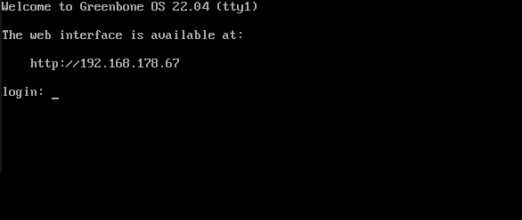
Fig. 6.1 Login prompt of the appliance
After the boot process is completed, the login prompt is shown (see Fig. 6.1).
6.1.3 Using the GOS Administration Menu
The GOS administration menu can be navigated using a keyboard.
The arrow keys of the keyboard are used for the menu selection.
Pressing Enter is used to confirm the current menu selection and to continue.
Pressing Space is used to toggle on/off switches.
The current menu can be exited by pressing Esc.
In most cases, changes made in the GOS administration menu are not activated immediately. Instead, the menu option Save is added below the other options (see Fig. 6.2). Select Save and press Enter to save changes.
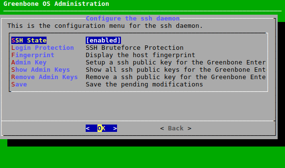
Fig. 6.2 New menu option for saving pending changes
If a menu is exited without saving the changes, a warning is displayed (see Fig. 6.3).
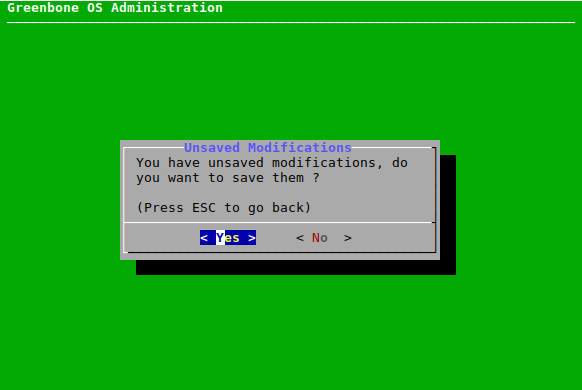
Fig. 6.3 Saving pending changes
6.2 Setup Menu
6.2.1 Managing Users
6.2.1.1 Changing the System Administrator Password
The password of the system administrator can be changed. This is especially important during the first basic configuration. The default setting is not suitable for a production environment.
The password can be changed as follows:
Select Setup and press Enter.
Select User and press Enter.
Select Password and press Enter (see Fig. 6.4).
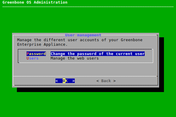
Fig. 6.4 Accessing the user management
Enter the current password and press Enter (see Fig. 6.5).
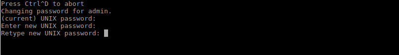
Fig. 6.5 Changing the system administrator password
Enter the new password and press Enter.
Note
Trivial passwords are rejected, including the default password
admin.Repeat the new password and press Enter.
Note
The change is effective immediately and a commit of the change is not required. A rollback is not possible either.
6.2.1.2 Managing Web Users
The GOS administration menu offers the possibility to manage web users (= user accounts for the appliance’s web interface and GMP API).
Note
There is no web interface for the appliance models Greenbone Enterprise 35 and Greenbone Enterprise 25V.
For these appliance models, this chapter and its subchapters are not relevant.
Note
To use the appliance’s web interface, at least one web administrator (= web user with the role Admin) must be created (see Chapter 6.2.1.3).
Web administrators which were created via the GOS administration menu do not have an owner and are so-called “global objects”. Sometimes they are also referred to as “global web users”. They can only be managed via the GOS administration menu or by a super administrator.
All web users can be displayed as follows:
Select Setup and press Enter.
Select User and press Enter.
Select Users and press Enter.
Select List Users and press Enter to display a list of all configured web users (see Fig. 6.6).
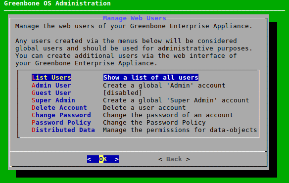
Fig. 6.6 Managing the web users
6.2.1.3 Creating a Web Administrator
To use the appliance’s web interface, at least one web administrator (= web user with the role Admin) must be created.
Note
The creation of the first web administrator is only possible using the GOS administration menu.
A web administrator can be created as follows:
Select Setup and press Enter.
Select User and press Enter.
Select Users and press Enter.
Select Admin User and press Enter.
Enter the user name for the web administrator (see Fig. 6.7).
Note
Only the following characters are allowed for the user name:
All alphanumeric characters
- (dash)
_ (underscore)
. (full stop)
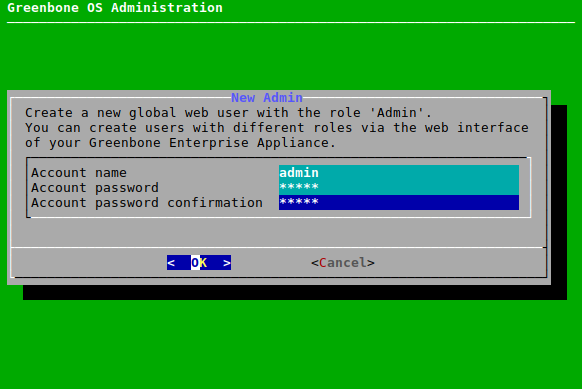
Fig. 6.7 Creating a new web administrator
Enter the password for the web administrator twice.
Note
The password can contain any type of character and can be at most 30 characters long.
When using special characters, note that these must be available on all used keyboards and correctly supported by all client software and operating systems. Copying and pasting special characters for passwords can lead to invalid passwords depending on these external factors.
Select OK and press Enter.
→ A message informs that the web administrator has been created.
Press Enter to close the message.
6.2.1.4 Enabling a Guest User
In order for a guest to log in without a password, the guest access must be enabled as follows:
Select Setup and press Enter.
Select User and press Enter.
Select Users and press Enter.
Select Guest User and press Enter.
Enter the user name and the password of an existing web user and press Tab.
Press Enter.
→ The web user is now allowed to log in to the web interface without needing the password (see Fig. 6.8).
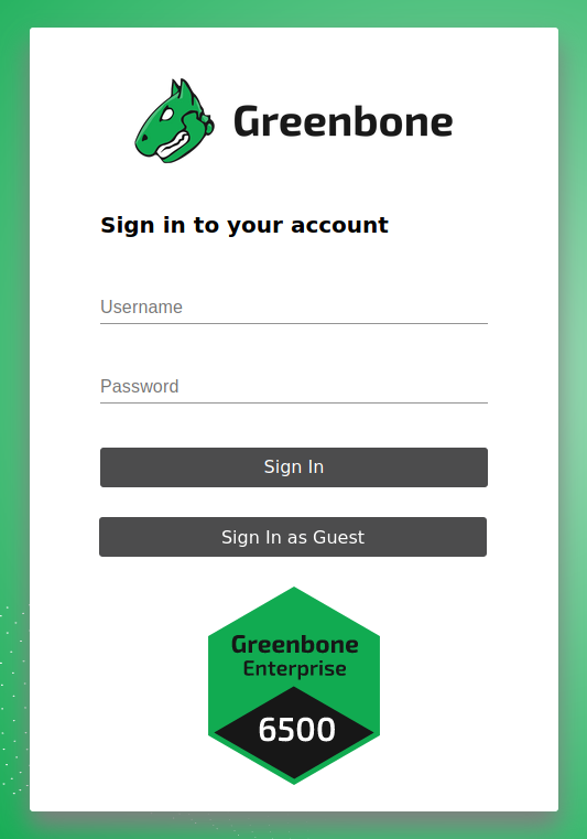
Fig. 6.8 Logging in as a guest user without password
6.2.1.5 Creating a Super Administrator
The role Super Admin is the highest level of access. A user with this role can be created as follows:
Select Setup and press Enter.
Select User and press Enter.
Select Users and press Enter.
Select Super Admin and press Enter.
→ A warning asks to confirm the process (see Fig. 6.9).
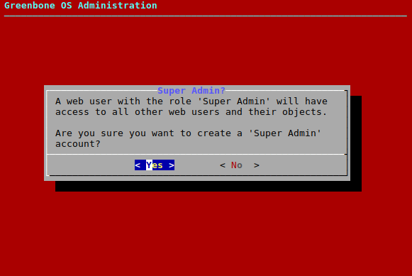
Fig. 6.9 Warning when creating a new super administrator
Select Yes and press Enter.
Enter the user name for the super administrator.
Note
Only the following characters are allowed for the user name:
All alphanumeric characters
- (dash)
_ (underscore)
. (full stop)
Enter the password for the super administrator twice.
Note
The password can contain any type of character and can be at most 30 characters long.
When using special characters, note that these must be available on all used keyboards and correctly supported by all client software and operating systems. Copying and pasting special characters for passwords can lead to invalid passwords depending on these external factors.
Select OK and press Enter.
→ A message informs that the super administrator has been created.
Press Enter to close the message.
Note
The super administrator can only be edited by the super administrator themself.
6.2.1.6 Deleting a User Account
Note
Super administrators can only be deleted as described here. Deleting a super administrator via the web interface is not possible.
The user who is Feed Import Owner cannot be deleted. Another Feed Import Owner must be set or the setting has to be unset first (see Chapter 6.2.1.10.1)
A web user can be deleted as follows:
Select Setup and press Enter.
Select User and press Enter.
Select Users and press Enter.
Select Delete Account and press Enter.
Select the web user that should be deleted and press Enter.
→ A message asks whether an inheritor should be chosen.
If an inheritor should be defined, select Yes and press Enter.
Select the web user that should be the inheritor and press Enter.
→ The web user is deleted immediately.
or
If no inheritor should be defined, select No and press Enter.
→ The web user is deleted immediately.
6.2.1.7 Limiting the Number of Concurrent Web Sessions
The same web user may log in to the web interface in multiple web sessions. It is possible to restrict the number of concurrent web sessions.
Select Setup and press Enter.
Select User and press Enter.
Select Users and press Enter.
Select User sessions and press Enter.
Enter the maximum number of concurrent web sessions in the input box (see Fig. 6.10).
Note
The value can be between
0and25. The default value is0, which means that the number of web sessions is unlimited.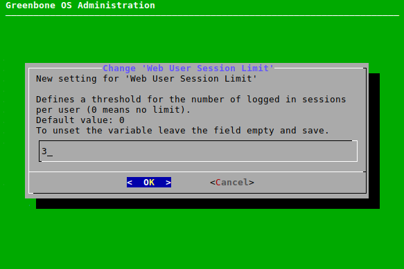
Fig. 6.10 Limiting the number of web sessions
Press Enter.
6.2.1.8 Changing a User Password
The password of a web user can be changed as follows:
Select Setup and press Enter.
Select User and press Enter.
Select Users and press Enter.
Select Change Password and press Enter.
Select the web user whose password should be changed and press Enter.
Enter the new password twice and press Tab (see Fig. 6.11).
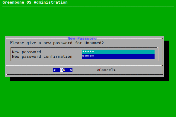
Fig. 6.11 Changing a user password
Press Enter.
6.2.1.9 Changing the Password Policy
The requirements for passwords can be changed as follows:
Select Setup and press Enter.
Select User and press Enter.
Select Users and press Enter.
Select Password Policy and press Enter.
Select Length and press Enter to set the minimum length of a password.
Note
The minimum length must be at least 10 characters.
Select Username and press Enter to determine whether user name and password can be the same.
Select Complex and press Enter to determine whether a password must contain at least one letter, one number and one symbol.
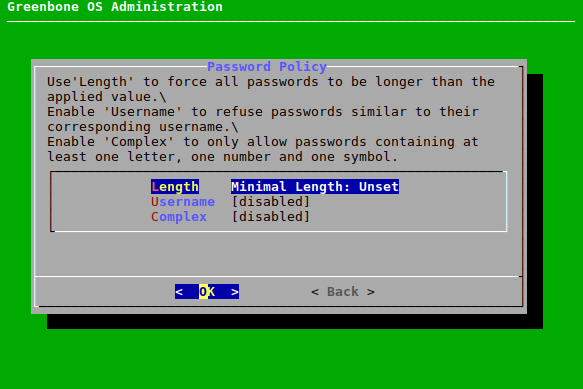
Fig. 6.12 Changing the password policy
6.2.1.10 Configuring the Settings for Data Objects
Scan configurations, compliance policies, report formats and port lists by Greenbone (hereafter referred to as “objects”) are distributed via the feed. These objects must be owned by a user, the Feed Import Owner.
The objects are downloaded and updated during a feed update if a Feed Import Owner has been set.
Only the Feed Import Owner, a super administrator and users who obtained respective rights are able to delete objects. If objects are deleted, they will be downloaded again during the next feed update.
Note
If the objects remain in the trashcan, they are not yet considered deleted and will not be downloaded again during the next feed update.
If no objects should be downloaded, the Feed Import Owner must be unset.
The Feed Import Owner, a super administrator (default role) and an administrator (default role) who currently has permissions for the objects may also grant additional permissions for the objects to other users (see Chapter 8.4.1.1 or 8.4.1.2). Normally, this only applies to the default roles. Custom roles must be granted permissions manually first.
6.2.1.10.1 Changing the Feed Import Owner
The Feed Import Owner is set during the first appliance setup (see Chapters 5 and 4). However, the Feed Import Owner can be changed at a later time.
Note
If the Feed Import Owner is changed, the ownership of the objects will be changed to the new Feed Import Owner the next time they are imported from the feed. The previous feed import owner continues to own the objects until then.
If the previous Feed Import Owner removes the objects, they will be imported during the feed update and owned by the new Feed Import Owner.
The Feed Import Owner can be changed as follows:
Select Setup and press Enter.
Select User and press Enter.
Select Users and press Enter.
Select Distributed Data and press Enter (see Fig. 6.13).
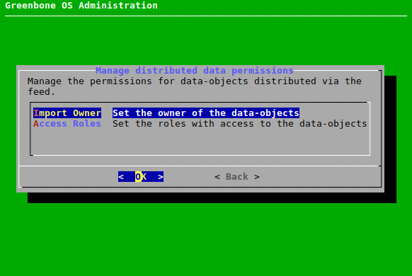
Fig. 6.13 Configuring the settings for the data objects
Select Import Owner and press Enter.
Select the user that should be Feed Import Owner and press Space.
Press Enter.
Note
The user who is Feed Import Owner cannot be deleted (see Chapter 6.2.1.6). Another Feed Import Owner or (Unset) must be selected.
6.2.1.10.2 Setting the Access Roles
By default, the roles User, Admin and Super Admin have read access to the objects, which means they can see and use them on the web interface.
However, the roles that should have read access to the objects can be selected as follows:
Select Setup and press Enter.
Select User and press Enter.
Select Users and press Enter.
Select Distributed Data and press Enter.
Select Access Roles and press Enter.
Select the roles that should be able to see and use the objects and press Space (see Fig. 6.14).
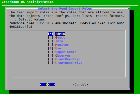
Fig. 6.14 Selecting the roles with read access to the objects
Press Enter.
6.2.2 Configuring the Network Settings
6.2.2.1 Updating the Networking Mode to gnm
If the old network mode is still active, a menu option for switching to the new network mode GOS Network Manager (gnm) is available. If the network mode gnm is already in use, the option is not displayed. Switching back to the old network mode is not possible.
The network mode can be switched as follows:
Select Setup and press Enter.
Select Network and press Enter.
Select Switch Networking Mode and press Enter.
→ A warning recommends to establish a console connection to the appliance before switching the network mode (see Fig. 6.15).

Fig. 6.15 Switching the network mode
Select Yes and press Enter.
→ When the process is finished, a message informs that the network mode was successfully updated to gnm.
6.2.2.2 General Information About Namespaces
Some appliance models (Greenbone Enterprise 5400/6500 and Greenbone Enterprise 400/450/600/650) have their network interfaces organized in different namespaces:
Management namespace
This namespace includes all interfaces required for management activities.
Only interfaces in the management namespace can handle management traffic. This includes accessing the GOS administration menu, the web interface, the Greenbone Feed Server, and configuring and operating master-sensor setups.
Scan namespace
This namespace includes all interfaces required for vulnerability scanning activities.
Interfaces in the scan namespace only handle scan traffic.
By default, all interfaces are in the management namespace. This enables both management and scan traffic on all interfaces. As soon as at least one interface is in the scan namespace, namespace separation goes into effect.
The namespaces are separated to connect only the interfaces in the scan namespace to networks accessible from the internet. In this way, attacks from the internet cannot reach the appliance’s management interfaces.
Tip
Separating the namespaces is recommended.
6.2.2.3 Switching an Interface to Another Namespace
Interfaces can be moved to another namespace as follows:
Select Setup and press Enter.
Select Network and press Enter.
Select Configure Namespaces and press Enter.
Press Enter.
Note
Interfaces that are currently in the scan namespace are marked with * (see Fig. 6.16).
Interfaces that are currently in the management namespace are labeled accordingly.
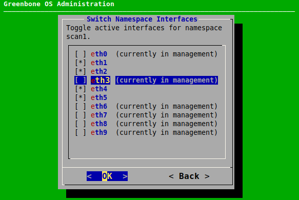
Fig. 6.16 Switching interfaces to another namespace
Select the interface that should be moved and and press Space.
Note
Not all interfaces may be moved to the scan namespace, otherwise the appliance will no longer be accessible.
Press Enter.
6.2.2.4 Configuring Network Interfaces
Note
At least one network interface must be configured to access the appliance via the network. Usually, the first network interface eth0 is used for this purpose. The administrator must configure this network interface and connect the appliance to the network.
On all virtual appliances, the first network interface is preconfigured with IPv4 via DHCP.
Network interfaces can be configured as follows:
Select Setup and press Enter.
Select Network and press Enter.
Select the namespace of the desired interface and press Enter.
Select Interfaces and press Enter.
Select the desired interface and press Enter.
Note
If there is only one interface in this namespace, the configuration of the interface is opened directly.
→ The interface can be configured (see Fig. 6.17).
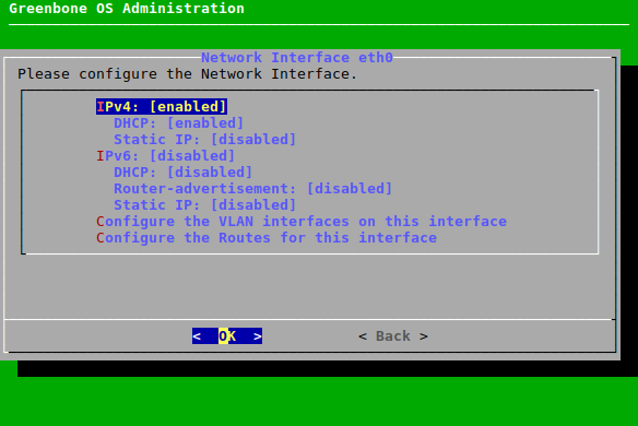
Fig. 6.17 Configuring the network interface
6.2.2.4.1 Setting up a Static IP Address
Select the desired interface (see Chapter 6.2.2.4).
Select Static IP (for IPv4 or IPv6) and press Enter.
Delete
dhcpfrom the input box and replace it with the correct IP address including the prefix length (see Fig. 6.18).Note
The static IP can be disabled by leaving the input box empty.
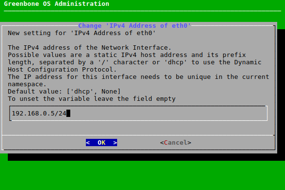
Fig. 6.18 Entering a static IP address
Press Enter.
→ A message informs that the changes must be saved.
Press Enter to close the message.
6.2.2.4.2 Configuring a Network Interface to Use DHCP
Note
When using DHCP, the appliance does not transmit the MAC address but a DHCP Unique ID (DUID). While this should not pose a problem with modern DHCP servers, some older DHCP servers (for example Windows Server 2012) may not be able to handle it.
One possible solution is to specify the DUID instead of the MAC address on the DHCP server. Alternatively, a static IP address can be used on the appliance.
A network interface can be configured to use DHCP as follows:
Select the desired interface (see Chapter 6.2.2.4).
Select DHCP (for IPv4 or IPv6) and press Enter.
6.2.2.4.3 Configuring the Maximum Transmission Unit (MTU)
Note
The configuration of the MTU is only possible if a static IP address is configured.
The MTU can be set as follows:
Select the desired interface (see Chapter 6.2.2.4).
Select MTU (for IPv4 or IPv6) and press Enter.
Enter the MTU in the input box.
Note
If the input box is left empty, the default value is set.
Press Enter.
→ A message informs that the changes must be saved.
Press Enter to close the message.
6.2.2.4.4 Using the Router Advertisement for IPv6
If the configuration of IP addresses and a global gateway for IPv6 should be done automatically via SLAAC (Stateless Address Autoconfiguration), router advertisement can be enabled as follows:
Select the desired interface (see Chapter 6.2.2.4).
Select Router-advertisement and press Enter.
6.2.2.4.5 Configuring VLANs
Note
VLAN interfaces are currently not supported on virtual appliances. If the hypervisor supports virtual switches, those can be used to realize the functionality.
Creating a New VLAN
A new VLAN subinterface can be created as follows:
Select the desired interface (see Chapter 6.2.2.4).
Select Configure the VLAN interfaces on this interface and press Enter.
Select Configure a new VLAN interface and press Enter.
Enter the VLAN ID in the input box and press Enter (see Fig. 6.19).
→ A message informs that the changes must be saved.
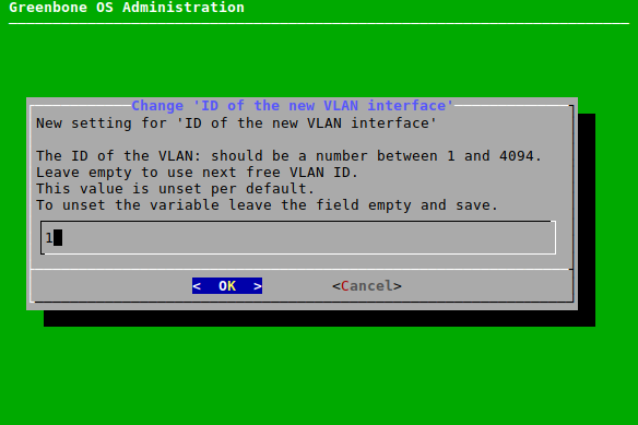
Fig. 6.19 Creating a new VLAN subinterface
Press Enter to close the message.
→ The new interface can be configured using IPv4 and IPv6 (see Fig. 6.20).
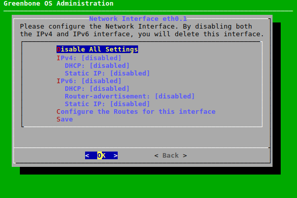
Fig. 6.20 Configuring the VLAN subinterface
Configuring a VLAN
All created subinterfaces can be configured as follows:
Select the desired interface (see Chapter 6.2.2.4).
Select Configure the VLAN interfaces on this interface and press Enter.
Select Configure the VLAN interface … for the desired subinterface.
Configure the subinterface as described in the subchapters of Chapter 6.2.2.4.
Note
The VLAN can be deleted by selecting Disable All Settings and pressing Enter.
6.2.2.4.6 Configuring the Routes for an Interface
Adding a New Route
A new route for an interface can be configured as follows:
Select the desired interface (see Chapter 6.2.2.4).
Select Configure the Routes for this interface and press Enter.
Select Configure IPv4 Routes or Configure IPv6 Routes and press Enter (see Fig. 6.21).
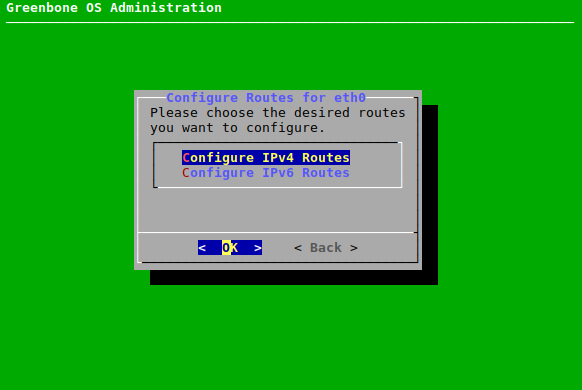
Fig. 6.21 Configuring routes for an interface
Select Add a new route and press Enter.
Enter the target network and the next hop in the input boxes, select OK and press Enter.
Configuring a Route
All created routes can be configured as follows:
Select the desired interface (see Chapter 6.2.2.4).
Select Configure the Routes for this interface and press Enter.
Select Configure IPv4 Routes or Configure IPv6 Routes and press Enter.
Select the desired route and press Enter.
Edit the route, select OK and press Enter.
6.2.2.5 Configuring the DNS Server
For receiving the feed and updates, the appliance requires a reachable and functioning DNS (Domain Name System) server for name resolution. This setting is not required if the appliance uses a proxy for downloading the feed and updates.
If DHCP is used for the configuration of the network interfaces, the DNS servers provided by the DHCP protocol are used.
The appliance supports up to three DNS servers. At least one DNS server is required. Additional servers will only be used if an outage of the first server occurs.
The DNS server can be configured as follows:
Select Setup and press Enter.
Select Network and press Enter.
Select Namespace: Management and press Enter.
Select DNS and press Enter.
Select the desired DNS server and press Enter.
Enter the IP address used as the DNS server in the input box and press Enter (see Fig. 6.22).
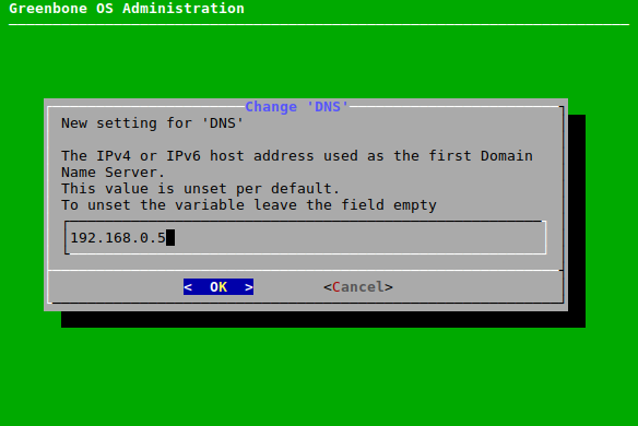
Fig. 6.22 Configuring the DNS server
→ A message informs that the changes must be saved.
Press Enter to close the message.
Note
Whether the DNS server can be reached and is functional can be determined by performing a self-check (see Chapter 6.3.1).
6.2.2.6 Configuring the Global Gateway
The global gateway is often called the default gateway.
It may be obtained automatically via DHCP or router advertisement.
If using DHCP to assign IP addresses, the global gateway will be set via DHCP unless it was set explicitly.
If SLAAC (Stateless Address Autoconfiguration) should be used with IPv6, router advertisement must be activated (see Chapter 6.2.2.4.4).
However, if the appliance is configured to use static IP addresses exclusively and access to other networks is desired, the gateway must be configured manually. Separate options are available for IPv4 and IPv6.
The global gateway can be configured as follows:
Select Setup and press Enter.
Select Network and press Enter.
Note
If the appliance has namespaces (see Chapter 6.2.2.2), the desired namespace has to be selected first.
If the appliance has no namespaces, continue with step 4.
Select the namespace for which the global gateway should be configured and press Enter.
Select Global Gateway for IPv4 or Global Gateway (IPv6) for IPv6 and press Enter.
Select the desired interface and press Enter (see Fig. 6.23).
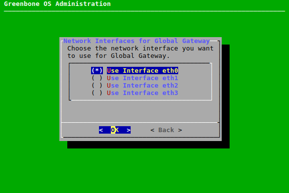
Fig. 6.23 Configuring the global gateway
Enter the IP address used as the global gateway in the input box and press Enter.
→ A message informs that the changes must be saved.
Press Enter to close the message.
6.2.2.7 Setting the Host Name and the Domain Name
When the appliance is delivered by Greenbone or after a factory reset, a default host and domain name are configured. Configuring a correct fully qualified domain name (FQDN) may be required depending on the setup in which the appliance is deployed, and is generally recommended.
The host name option is used to configure the short host name, and the domain name option is used for the domain name including its suffix. The two values combined form the FQDN. The default values are:
Host name: gsm
Domain name: gbuser.net
The currently configured domain name is always used as a search domain. DHCP servers can add search domains if DHCP is configured for at least one network interface of the appliance, and if the DHCP server is configured accordingly. GOS does not provide any further configuration options to add more custom search domains.
The host name and the domain name can be configured as follows:
Select Setup and press Enter.
Select Network and press Enter.
Select Namespace: Management and press Enter.
Select Hostname or Domainname and press Enter.
Enter the host name or the domain name in the input box and press Enter (see Fig. 6.24).
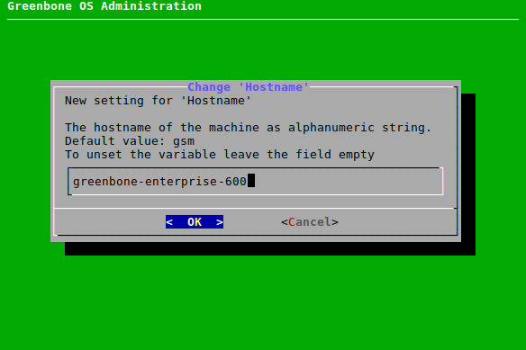
Fig. 6.24 Setting the host name/domain name
→ A message informs that the changes must be saved.
Press Enter to close the message.
6.2.2.8 Restricting the Management Access
The IP address under which the management interface is available can be set.
All administrative access (SSH, HTTPS, GMP) will be restricted to the respective interface and will not be available on the other interfaces.
Note
This feature overlaps with the namespace separation (see Chapter 6.2.2). Namespace separation is recommended.
If no IP address is set, the management interface will be available on all IP addresses of the interfaces in the management namespace.
The IP address for the management interface can be set as follows:
Select Setup and press Enter.
Select Network and press Enter.
Select Namespace: Management and press Enter.
Select Management IP (v4) or Management IP (v6) and press Enter.
Enter the IP address for the management interface in the input box and press Enter (see Fig. 6.25).
Note
The IP address must be the IP address of one of the interfaces in the management namespace. If any other IP address is set, the management interface will not be available.
Either the IP address or the name of the interface (for example
eth0) can be entered.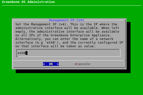
Fig. 6.25 Restricting the management access
6.2.2.9 Displaying the MAC and IP Addresses and the Network Routes
The used MAC addresses, the currently configured IP addresses and the appliance’s network routes can be displayed in a simple overview.
Note
This does not support the configuration of the MAC addresses.
The MAC addresses, IP addresses or network routes can be displayed as follows:
Select Setup and press Enter.
Select Network and press Enter.
Select the namespace for which the IP addresses, MAC addresses or network routes should be displayed and press Enter.
Select MAC, IP or Routes and press Enter.
→ The MAC/IP addresses or the network routes of the selected namespace are displayed (see Fig. 6.26).
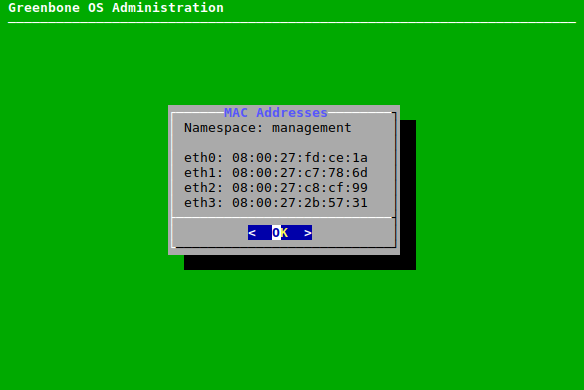
Fig. 6.26 Displaying the MAC/IP addresses or network routes
6.2.3 Configuring a Virtual Private Network (VPN) Connection
OpenVPN is integrated in GOS. The VPN feature allows scanning of targets reachable through the VPN tunnel, but has no effect on other targets, network settings, or master-sensor connections.
Note
Scanning through a VPN tunnel is only available for the appliance models Greenbone Enterprise DECA/TERA/PETA/EXA (see Chapter 3).
To run scans through a VPN tunnel, a VPN connection must be set up. The VPN tunnel is always initiated from the appliance side.
A PKCS#12 file with the following requirements is needed to authenticate the appliance in the VPN:
The PKCS#12 file must contain the necessary certificate, and private key files.
The PKCS#12 file may contain a certificate authority (CA) file. If it does not contain one, the CA file must be imported separately.
The PKCS#12 file may be password protected or not.
Password-protected private key files within the PKCS#12 file are not supported.
6.2.3.1 Setting up a VPN Connection
Note
Only one VPN connection can be set up at a time.
A new VPN connection can be set up as follows:
Select Setup and press Enter.
Select VPN and press Enter.
Select Add a new VPN and press Enter (see Fig. 6.27).
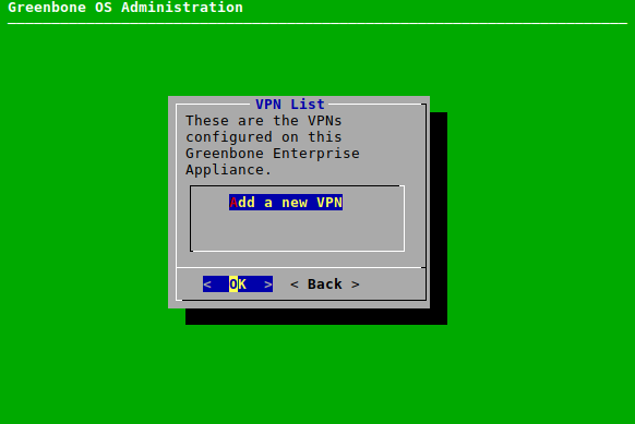
Fig. 6.27 Adding a VPN connection
Enter the VPN’s IP address in the input box and press Enter.
Open the web browser and enter the displayed URL.
Click Browse…, select the PKCS#12 container and click Upload.
If an export password was used to protect the PKCS#12 container, enter the password and press Enter.
→ A message informs that the PKCS#12 file was successfully extracted.
Press Enter.
Note
If the PKCS#12 file does not contain a CA file, the CA file must be imported separately.
If the PKCS#12 file already contains a CA file, a CA file can also be imported separately, but this overwrites the CA file from the PKCS#12 file.
Select Certificate Authority and press Enter.
Open the web browser and enter the displayed URL.
Click Browse…, select the CA file and click Upload.
→ A message informs that the CA file was imported successfully.
Press Enter.
→ The VPN connection is established and targets reachable via the VPN can be scanned (see Chapter 9.2).
6.2.3.2 Editing or Deleting a VPN Connection
The VPN connection can be edited as follows:
Select Setup and press Enter.
Select VPN and press Enter.
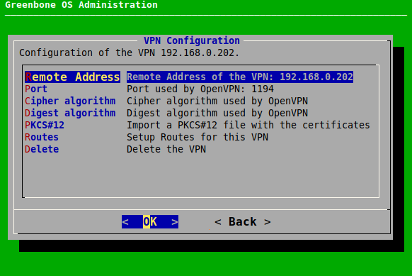
Fig. 6.28 Editing or deleting a VPN connection
The following actions are available:
- Remote Address
Define the VPN’s IP address.
- Port
Define the port used by OpenVPN. By default, the port is 1194.
- Cipher algorithm
Select the cipher algorithm. By default, the default setting of OpenVPN is used.
- Digest algorithm
Select the digest algorithm. By default, the default setting of OpenVPN is used.
- PKCS#12
Replace the PKCS#12 file.
- Routes
Add a route for the VPN connection. Target IP address, net mask and target gateway must be defined.
Note
Only one route can be set up for the VPN connection.
- Delete
Delete the VPN connection.
6.2.4 Configuring Services
To access the appliance remotely, many interfaces are available:
HTTPS, see Chapter 6.2.4.1
Greenbone Management Protocol (GMP), see Chapter 14
Open Scanner Protocol (OSP), see Chapter 6.2.4.3
SSH, see Chapter 6.2.4.4
SNMP, see Chapter 6.2.4.5
6.2.4.1 Configuring HTTPS
The web interface is the usual option for creating, running and analyzing vulnerability scans. It is enabled by default and cannot be disabled.
An HTTPS certificate is required for using the web interface.
The web interface is securely configured with the factory settings provided by Greenbone, but security can be further enhanced with the configuration options described in this chapter.
6.2.4.1.1 Configuring the Timeout of the Web Interface
If no action is performed on the web interface for a defined period of time, the user is logged out automatically. The timeout value can be set as follows:
Select Setup and press Enter.
Select Services and press Enter.
Select HTTPS and press Enter.
Select Timeout and press Enter.
Enter the desired timeout value in the input box and press Enter (see Fig. 6.29).
Note
The value can be between 1 and 1440 minutes (1 day). The default value is 15 minutes.
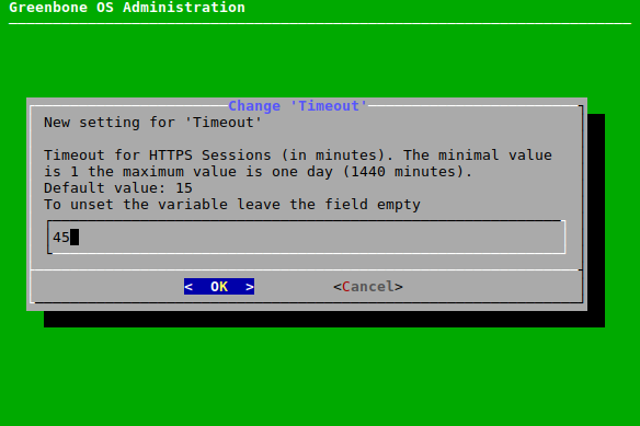
Fig. 6.29 Setting the timeout value
→ A message informs that the changes must be saved.
Press Enter to close the message.
6.2.4.1.2 Configuring the TLS Protocols
The TLS protocols for the HTTPS connection of the web interface can be configured as follows:
Select Setup and press Enter.
Select Services and press Enter.
Select HTTPS and press Enter.
Select Protocols and press Enter.
Select the desired protocol version and press Space (see Fig. 6.30).
Note
By default, both versions are selected.
If TLSv1.2 is selected (either alone or in combination with version 1.3), the ciphers for the HTTPS connection can be configured (see Chapter 6.2.4.1.3).
If only TLSv1.3 is selected, the default value for
-ciphersuites valof OpenSSL for the cipher suites is used. In this case, the menu option for configuring the ciphers is not available.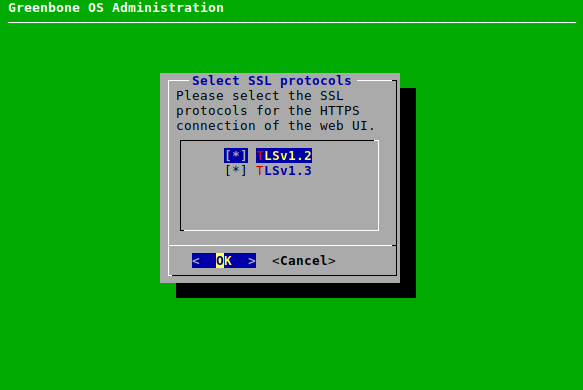
Fig. 6.30 Configuring the TLS protocols for the HTTPS connection
Select OK and press Enter.
6.2.4.1.3 Configuring the Ciphers
If TLS version 1.2 is used for the HTTPS connection of the web interface (either alone or in combination with version 1.3, see Chapter 6.2.4.1.2), the HTTPS ciphers can be configured to further enhance the security of the web interface.
Note
The current setting only allows secure ciphers using at least 128 bit key length, explicitly disallowing the cipher suites used by SSLv3 and TLSv1.0.
No ciphers exist for TLSv1.1.
The HTTPS ciphers can be configured as follows:
Select Setup and press Enter.
Select Services and press Enter.
Select HTTPS and press Enter.
Select Ciphers and press Enter.
Enter the desired value in the input box and press Enter (see Fig. 6.31).
Note
The string used to define the ciphers is validated by OpenSSL and must comply with the syntax of an OpenSSL cipher list.
More information about the syntax can be found here.
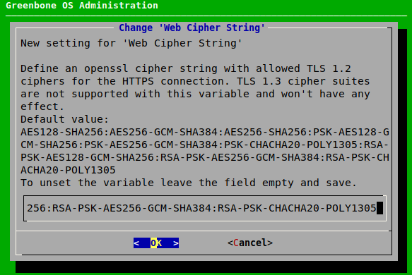
Fig. 6.31 Configuring the ciphers
→ A message informs that the changes must be saved.
Press Enter to close the message.
6.2.4.1.4 Configuring the Diffie-Hellman (DH) Parameters
DH parameters are used by the web server for establishing TLS connections. To further enhance the security of the web interface, new DH parameters can be generated as follows:
Select Setup and press Enter.
Select Services and press Enter.
Select HTTPS and press Enter.
Select DH Parameters and press Enter.
Select the desired key size and press Space.
Press Enter.
→ A message informs that the generation was started in the background.
Tip
The currently running system operation can be displayed by selecting About and pressing Enter in the GOS administration menu.
6.2.4.1.5 Configuring HTTP STS
To further enhance the security of the web interface, HTTP Strict Transport Security (HSTS) can be enabled. For HSTS to work, an HTTPS certificate signed by a certificate authority (CA) is required (see Chapter 6.2.4.1.7.2).
Enabling HSTS
HSTS can be enabled as follows:
Select Setup and press Enter.
Select Services and press Enter.
Select HTTPS and press Enter.
Select HTTP STS and press Enter to enable or disable HSTS.
Setting the Maximum Allowed Age of the HSTS Header
When HTTP STS is enabled, the maximum allowed age for the HSTS header can be set as follows:
Select Setup and press Enter.
Select Services and press Enter.
Select HTTPS and press Enter.
Select HTTP STS max age and press Enter.
Enter the maximum age in seconds in the input box and press Enter (see Fig. 6.32).
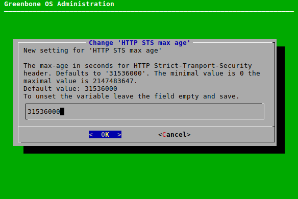
Fig. 6.32 Setting the maximum allowed age for the HTTP STS header
→ A message informs that the changes must be saved.
Press Enter to close the message.
6.2.4.1.6 Configuring OCSP Stapling
OCSP (Online Certificate Status Protocol) stapling is used for checking the validity status of X.509 digital certificates. It allows the certified party to perform the certificate validation by appending a time-stamped OCSP response signed by the certificate authority (CA) to the original TLS handshake (“stapling”).
OCSP stapling can be enabled as follows:
Select Setup and press Enter.
Select Services and press Enter.
Select HTTPS and press Enter.
Select OCSP Stapling and press Enter to enable or disable OCSP Stapling.
6.2.4.1.7 Managing Certificates
The appliance basically uses two types of certificates:
Self-signed certificates
Certificates issued by an external certificate authority (CA)
All modern operating systems support the creation and management of their own CA.
Under Microsoft Windows Server, the Active Directory Certificate Services support the administrator in the creation of a root CA.
For Linux systems, various options are available. One option is described in the IPSec-Howto.
Note
It must be verified how the systems are accessed later before creating the certificate.
The IP address or the DNS name is stored when creating the certificate.
Displaying the Current Certificate
The current certificate can be displayed as follows:
Select Setup and press Enter.
Select Services and press Enter.
Select HTTPS and press Enter.
Select Certificate and press Enter.
Select Show and press Enter.
→ The certificte is displayed.
6.2.4.1.7.1 Self-Signed Certificates
The use of self-signed certificates is the easiest way. It poses, however, the lowest security and more work for the user:
The trustworthiness of a self-signed certificate can only be checked manually by the user through importing the certificate and examining its fingerprint.
Self-signed certificates cannot be revoked. Once they are accepted by the user, they are stored permanently in the browser. If an attacker gains access to the corresponding private key, a man-in-the-middle attack on the connection protected by the certificate can be launched.
To support a quick setup, the appliance supports self-signed certificates.
For most appliance models, such a certificate is not installed by default and must be created.
Only the Greenbone Enterprise ONE already comes with a pre-installed certificate.
Creating a Self-Signed Certificate
Self-signed certificates can be created as follows:
Select Setup and press Enter.
Select Services and press Enter.
Select HTTPS and press Enter.
Select Certificate and press Enter.
Select Generate and press Enter.
→ A message informs that the current certificate and private key will be overwritten.
Confirm the message by selecting Yes and pressing Enter.
Provide the settings for the certificate (see Fig. 6.33), select OK and press Enter.
Note
It is valid to generate a certificate without a common name. However, a certificate should not be created without (a) Subject Alternative Name(s) (SAN).
If a common name is used, it should be the same as one of the SANs.
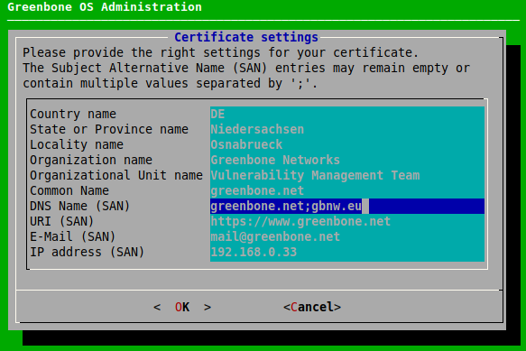
Fig. 6.33 Providing settings for the certificate
→ When the process is finished, a message informs that the certificate can be downloaded.
Press Enter to close the message.
Select Download and press Enter.
Open the web browser and enter the displayed URL.
Download the PEM file.
In the GOS administration menu, press Enter.
→ When the certificate is retrieved by the appliance, the GOS administration menu displays the fingerprint of the certificate for verification.
Check the fingerprint and confirm the certificate by pressing Enter.
6.2.4.1.7.2 Certificate by an External Certificate Authority (CA)
The use of a certificate issued by a CA has several advantages:
All clients trusting the CA can verify the certificate directly and establish a secure connection. No warning is displayed in the browser.
The certificate can be revoked easily by the CA. If the clients have the ability to check the certificate status, they can decline a certificate that may still be within its validity period but has been revoked. As mechanisms, the Certificate Revocation Lists (CRLs) or Online Certificate Status Protocol (OCSP) can be used.
Especially if multiple systems within an organization serve SSL/TLS protected information, the use of an organizational CA simplifies the management drastically. All clients simply have to trust the organizational CA to accept all certificates issued by the CA.
To import a certificate by an external CA, two options are available:
Generate a certificate signing request (CSR) on the appliance, sign it via an external CA and import the certificate.
Generate the CSR and the certificate externally and import both using a PKCS#12 file.
Generating a CSR and Importing a Certificate
Note
The appliance’s web interface cannot be used while waiting for CA to process the CSR. Only after the signed certificate has been imported, the web interface is accessible again.
A new CSR can be created and the certificate can be imported as follows:
Select Setup and press Enter.
Select Services and press Enter.
Select HTTPS and press Enter.
Select Certificate and press Enter.
Select CSR and press Enter.
→ A message informs that the current certificate and private key will be overwritten.
Confirm the message by selecting Yes and pressing Enter.
Provide the settings for the certificate (see Fig. 6.34), select OK and press Enter.
Note
It is valid to generate a certificate without a common name. A certificate should not be created without (a) Subject Alternative Name(s).
If a common name is used, it should be the same as one of the SANs.

Fig. 6.34 Providing settings for the certificate
Open the web browser and enter the displayed URL.
Download the PEM file.
→ The GOS administration menu displays a message to verify that the CSR has not been tampered with.
Verify the information by pressing Enter.
When the certificate was signed by the CA, select Certificate and press Enter.
Open the web browser and enter the displayed URL.
Click Browse…, select the signed certificate and click Upload.
→ When the certificate is retrieved by the appliance, the GOS administration menu displays the fingerprint of the certificate for verification.
Check the fingerprint and confirm the certificate by pressing Enter.
Importing an Already Existing Certificate
If a private key and a signed certificate already exist, they can be imported. The private key and the certificate must be formatted as a PKCS#12 file. The file can be protected with an export password.
The PKCS#12 file can be imported as follows:
Select Setup and press Enter.
Select Services and press Enter.
Select HTTPS and press Enter.
Select Certificate and press Enter.
Select PKCS#12 and press Enter.
→ A message informs that the current certificate and private key will be overwritten.
Confirm the message by selecting Yes and pressing Enter.
Open the web browser and enter the displayed URL.
Click Browse…, select the PKCS#12 container and click Upload.
Note
If an export password is used to protect the PKCS#12 container, the password must be entered.
→ When the certificate is retrieved by the appliance, the GOS administration menu displays the fingerprint of the certificate for verification.
Check the fingerprint and confirm the certificate by pressing Enter.
6.2.4.1.8 Displaying Fingerprints
The fingerprints of the used certificate can be displayed and checked as follows:
Select Setup and press Enter.
Select Services and press Enter.
Select HTTPS and press Enter.
Select Fingerprints and press Enter.
→ The following fingerprints of the currently active certificate are displayed:
SHA1
SHA256
BB
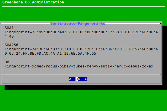
Fig. 6.35 Displaying the fingerprints
6.2.4.2 Configuring the Greenbone Management Protocol (GMP)
The Greenbone Management Protocol (GMP) can be used for the communication of in-house software with the appliance.
GMP can be activated using the GOS administration menu as follows:
Note
The SSH service must be enabled before GMP can be enabled (see Chapter 6.2.4.4).
Select Setup and press Enter.
Select Services and press Enter.
Select GMP and press Enter.
Press Enter to enable or disable GMP (see Fig. 6.36).
→ A message informs that the changes must be saved.
Press Enter to close the message.
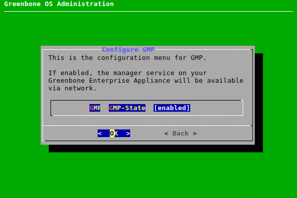
Fig. 6.36 Enabling GMP
6.2.4.3 Configuring the Open Scanner Protocol (OSP)
The Open Scanner Protocol (OSP) is required for the master-sensor communication (see Chapter 15).
OSP can be activated using the GOS administration menu as follows:
Note
The SSH service must be enabled before OSP can be enabled (see Chapter 6.2.4.4).
Select Setup and press Enter.
Select Services and press Enter.
Select OSP and press Enter.
Press Enter to enable or disable OSP.
→ A message informs that the changes must be saved.
Press Enter to close the message.
6.2.4.4 Configuring SSH
SSH allows secure and remote access to the appliance’s GOS administration menu and command line over an unsecured network. Additionally, it is required for the master-sensor communication (see Chapter 15).
By default, SSH is disabled on the appliance and must be activated first, for example by using the serial console. In addition, an SSH client is required to connect to the appliance.
When connecting to the appliance with an SSH client, the following key exchange methods are supported:
ecdh-sha2-nistp256
ecdh-sha2-nistp384
ecdh-sha2-nistp521
curve25519-sha256
curve25519-sha256@libssh.org
When connecting from the appliance to another system, the supported methods depend both on the other system and the appliance. There are many possible combinations, which would go beyond the scope of this documentation.
6.2.4.4.1 Enabling the SSH State
The SSH server embedded in the appliance can be enabled as follows:
Select Setup and press Enter.
Select Services and press Enter.
Select SSH and press Enter.
Select SSH State and press Enter to enable SSH.
6.2.4.4.2 Enabling and Managing a Login Protection
A login protection can be enabled, which means that if a number of consecutive login attempts fail, the user will be locked.
Note
A self-scan, which means that a scan where the appliance is part of the scan target, may trigger the login protection.
The login protection does not block logging in via SSH admin key if such a key is set up (see Chapter 6.2.4.4.3).
Setting Up the Login Protection
The login protection can be enabled and managed as follows:
Select Setup and press Enter.
Select Services and press Enter.
Select SSH and press Enter.
Select Login Protection and press Enter.
Select Login Protection and press Enter (see Fig. 6.37).
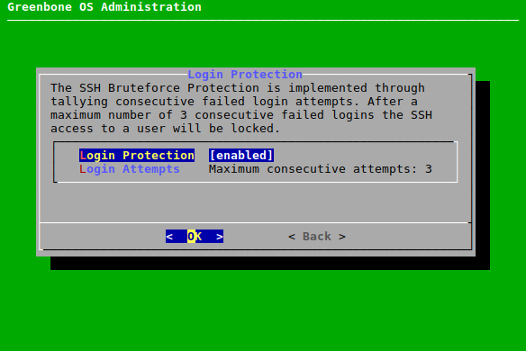
Fig. 6.37 Setting a login protection
→ A message informs that the login protection can lead to a locked SSH access.
Select Continue and press Enter to enable the login protection.
Select Login Attempts and press Enter.
Enter the desired value and press Enter.
→ A message informs that the changes must be saved.
Press Enter to close the message.
Unlocking a Locked System
In case the system is locked after too many failed login attempts, it must be unlocked using console access (serial, hypervisor or monitor/keyboard) as follows:
Select Setup and press Enter.
Select User and press Enter.
Select Unlock SSH and press Enter.
→ The login attempt counter is reset.
Press Enter to close the message.
6.2.4.4.3 Adding an SSH Admin Key
SSH public keys can be uploaded to enable key-based authentication of administrators.
Note
SSH keys can be generated with OpenSSH using the command
ssh-keygenon Linux orputtygen.exeif using PuTTY on Microsoft Windows.The following formats are supported:
Ed25519, for example
ssh-ed25519 AAAAB3NzaC1y...P3pCquVb admin@greenboneRSA, for example
ssh-rsa AAAAB3NzaC1y...P3pCquVb admin@greenbone
An SSH admin key can be uploaded as follows:
Select Setup and press Enter.
Select Services and press Enter.
Select SSH and press Enter.
Select Admin Key and press Enter.
Open the web browser and enter the displayed URL (see Fig. 6.38).
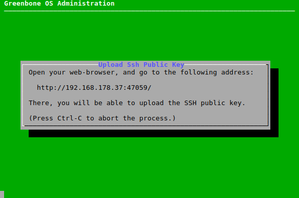
Fig. 6.38 Uploading an SSH public key
Click Browse…, select the SSH public key and click Upload.
→ When the upload is completed, a message informs that the login via SSH is possible.
6.2.4.4.4 Displaying Fingerprints
The appliance provides different host keys for its own authentication. The client decides which public key to use.
The fingerprints of the public keys used by the appliance’s SSH server can be displayed as follows:
Select Setup and press Enter.
Select Services and press Enter.
Select SSH and press Enter.
Select Fingerprint and press Enter.
→ The SHA256 fingerprints of the following keys are displayed:
Ed25519
RSA
6.2.4.5 Configuring SNMP
The appliance supports SNMPv3 for read access, and SNMPv1 for sending traps through alerts and monitoring vital parameters of the appliance.
The supported parameters are specified in a Management Information Base (MIB) file. The current MIB is available in the Greenbone TechDoc Portal.
SNMPv3 can be configured as follows:
Select Setup and press Enter.
Select Services and press Enter.
Select SNMP and press Enter.
Select SNMP and press Enter to enable SNMP.
→ Several new options are displayed (see Fig. 6.39).
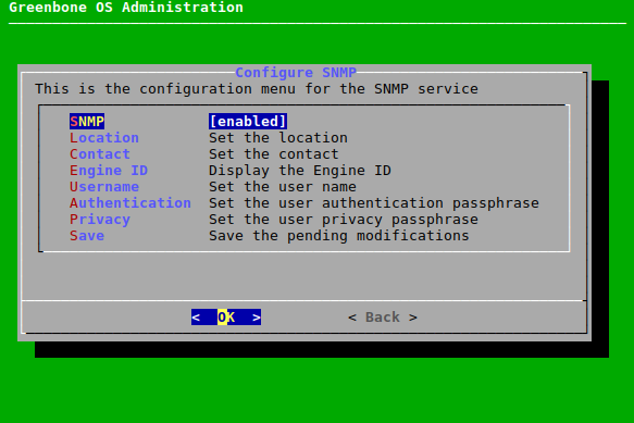
Fig. 6.39 Configuring SNMPv3
Select Location and press Enter.
Enter the location of the SNMP service in the input box and press Enter.
Select Contact and press Enter.
Enter the contact of the SNMP service in the input box and press Enter.
Select Username and press Enter.
Enter the SNMP user name in the input box and press Enter.
Note
When configuring the authentication and privacy passphrase, note that the appliance uses SHA-1 and AES128 respectively.
Select Authentication and press Enter.
Enter the SNMP user authentication passphrase in the input box and press Enter.
Select Privacy and press Enter.
Enter the SNMP user privacy passphrase in the input box and press Enter.
Note
After a user has been configured, the appliance’s engine ID can be displayed by selecting Engine ID and pressing Enter.
Afterwards, test the read access of the SNMP service under Linux/Unix using
snmpwalk:
$ snmpwalk -v 3 -l authPriv -u user -a sha -A password -x aes -X key 192.168.222.115
iso.3.6.1.2.1.1.1.0 = STRING: "Greenbone Enterprise Appliance"
iso.3.6.1.2.1.1.3.0 = Timeticks: (347275248) 40 days, 4:39:12.48
iso.3.6.1.2.1.1.4.0 = STRING: "Greenbone AG <info@greenbone.net>"
...
The following information can be gathered:
Uptime
Network interfaces
Memory
Harddisk
Load
CPU
6.2.4.6 Configuring a Port for the Temporary HTTP Server
By default, the port for HTTP uploads and downloads is randomly selected.
A permanent port can be configured as follows:
Select Setup and press Enter.
Select Services and press Enter.
Select Temporary HTTP and press Enter.
Select Port and press Enter.
Enter the port in the input box and press Enter.
→ A message informs that the changes must be saved.
Press Enter to close the message.
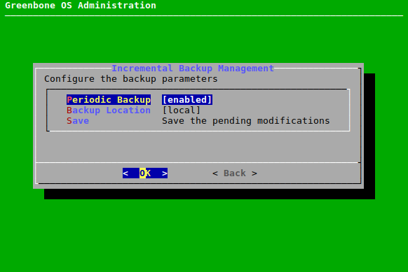
6.2.5 Configuring Periodic Backups
The appliance supports periodic, automatic daily backups. The backups are incremental backups which means that only data that was changed since the last backup is saved.
The following backups are stored locally or remotely:
Last 7 daily backups
Last 5 weekly backups
Last 12 monthly backups
Backups older than one year will be deleted automatically.
The periodic backups are automatically carried out at the following times:
6.2.5.1 Enabling Periodic Backups
Periodic backups can be enabled as follows:
6.2.5.2 Setting up a Remote Backup Server
By default, backups are stored locally. To store them on a remote server, the server must be set up appropriately. The appliance uses the SSH File Transfer Protocol (SFTP) to securely transfer the backups.
The remote server can be set up as follows:
Select Setup and press Enter.
Select Backup and press Enter.
Select Backup Location and press Enter.
→ More options for the backup location are added (see Fig. 6.41).
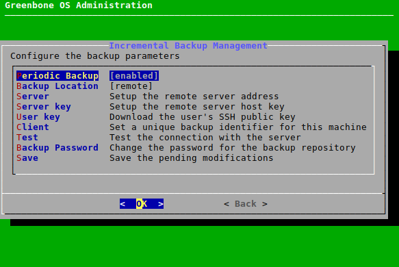
Fig. 6.41 Setting up the remote server
Select Server and press Enter.
Enter the remote server address in the following format:
username@hostname[:port]/directoryNote
The optional port may be omitted if the server uses port 22.
Select OK and press Enter.
→ A message informs that the changes must be saved.
Press Enter to close the message.
Note
The appliance uses an SSH host public key to identify the remote server.
The key must be looked up on the remote backup server. On Linux and most Unix-like systems, it can be found under
/etc/ssh/ssh_host_*_key.pub.The key must be in the OpenSSH Public Key Format.
The expected structure is
<algorithm> <key> <comment>.The
<key>section must be Base64 encoded.The
<comment>section is optional.Example:
ssh-rsa AAAAB3NzaC1y...P3pCquVb
Select Server key and press Enter.
Open the web browser and enter the displayed URL (see Fig. 6.42).
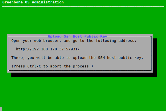
Fig. 6.42 Setting up the server key
Click Browse…, select the SSH host public key and click Upload.
Note
The appliance uses an SSH public key to log in on the remote server. To enable this login process, the SSH public key of the appliance must be enabled in the
authorized_keysfile on the remote server.To download the public key, select User key and press Enter.
Open the web browser and enter the displayed URL.
Download the PUB file.
Note
If several appliances upload their backups to the same remote server, the files must be distinguishable. For this, a unique backup identifier must be defined. If this identifier is not set, the host name will be used.
Select Client and press Enter.
Enter the identifier and press Enter.
Note
Since the setup of the remote backup including the keys is error-prone, a test routine is available. This option will test the successful login to the remote system.
Select Test and press Enter.
→ The login to the remote system is tested.
Note
Optionally, the backup repository password can be changed, which is recommended.
If multiple appliances use the same remote backup repository, it is recommended that each appliance uses its own unique backup password.
Select Backup Password and press Enter.
Enter the password in the input box and press Enter.
6.2.6 Configuring Special Upgrade Settings
6.2.6.1 Adding an Upgrade Key
This option is intended for possible recovery purposes. Uploading an upgrade key is not required for normal appliance operation and should only be done when instructed by Greenbone. Greenbone will provide the upgrade key in such a case.
Note
The key is automatically removed when GOS is upgraded successfully.
Adding an Upgrade Key Using the Editor
The key can be added using the editor as follows:
Select Setup and press Enter.
Select Upgrade and press Enter.
Select New Upgrade Key (Editor) and press Enter (see Fig. 6.43).
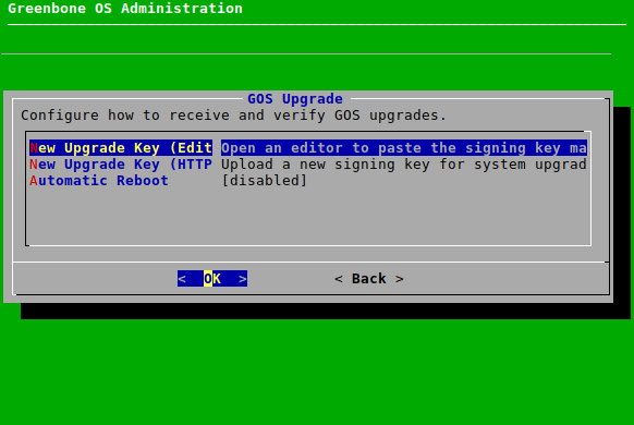
Fig. 6.43 Uploading an upgrade key
→ The editor is opened.
Enter the content of the upgrade key.
Note
It is important to enter the content of the key and not the name of the key (for example
GBFeedSigningKeyUntil2026.gpg.asc).The content of the key can be displayed with any text editor or under Linux using the program
less. If the content is opened with a text editor, care must be taken to not change anything.Press Ctrl + S to save the changes.
Press Ctrl + X to close the editor.
→ A message informs that the upgrade key was uploaded successfully.
Press Enter to close the message.
→ Both menu options for uploading a key are hidden temporarily. Instead, the menu option Delete Upgrade Key is displayed (see Chapter 6.2.6.2).
Adding an Upgrade Key via HTTP
The key can be added via HTTP as follows:
Select Setup and press Enter.
Select Upgrade and press Enter.
Select New Upgrade Key (HTTP) and press Enter (see Fig. 6.43).
Open the web browser and enter the displayed URL.
Click Browse…, select the upgrade key and click Upload.
→ A message informs that the upgrade key was successfully uploaded.
Press Enter to close the message.
→ Both menu options for uploading a key are hidden temporarily. Instead, the menu option Delete Upgrade Key is displayed (see Chapter 6.2.6.2).
6.2.6.2 Deleting an Upgrade Key
An upgrade key can be deleted as follows:
Select Setup and press Enter.
Select Upgrade and press Enter.
Select Delete Upgrade Key and press Enter.
→ A message informs that the upgrade key was deleted.
Press Enter to close the message.
6.2.6.3 Configuring the Automatic Reboot
The appliance may reboot automatically after a successful GOS upgrade. However, a reboot is only performed when required, for example if the GOS Linux kernel is upgraded.
The automatic reboot is disabled by default. In this case, after a GOS upgrade that requires a reboot, a self-check warning is displayed asking to reboot manually.
Note
This setting applies only to the appliance on which it is configured. It does not apply to all sensors connected to the appliance. If sensors should reboot automatically, each sensor must be configured separately.
Select Setup and press Enter.
Select Upgrade and press Enter.
Select Automatic Reboot and press Enter.
→ A warning informs that the appliance will reboot immediately after a GOS upgrade (see Fig. 6.44).
Note
All scans running at that time will be terminated. This can lead to the loss of unsaved data.
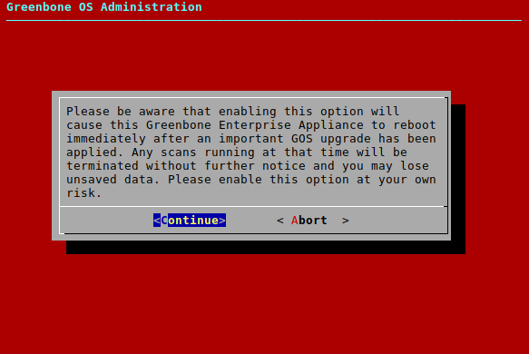
Fig. 6.44 Enabling automatic reboot
Select Continue and press Enter.
6.2.7 Configuring the Feed Synchronization
The Greenbone Enterprise Feed provides updates to vulnerability tests (VT), SCAP data (CVE and CPE) and CERT-Bund and DFN-CERT advisories. Additionally, the feed provides upgrades for GOS as well as updates for scan configurations, compliance policies, port lists and report formats.
A subscription key is required to to download and use the Greenbone Enterprise Feed (see Chapter 6.1.1). If no valid key is stored on the appliance, the public Greenbone Community Feed is used instead of the Greenbone Enterprise Feed.
Note
The model Greenbone Basic Appliance cannot be used with the Greenbone Community Feed.
6.2.7.1 Adding a Greenbone Enterprise Feed Subscription Key
Note
It is not necessary to add a Greenbone Enterprise Feed subscription key on a newly delivered appliance since a key is already pre-installed. As an exception, the model Greenbone Basic Appliance does not come with a pre-installed subscription key and cannot be used with the Greenbone Community Feed.
Whether a subscription key is already present on the appliance can be displayed by selecting About and pressing Enter in the GOS administration menu.
A new subscription key can be stored on the appliance by either uploading it via HTTP or by copying and pasting it using an editor.
For information about the subscription key see Chapter 6.1.1.
Note
The new key will overwrite any key already stored on the appliance.
When the subscription key is overwritten, the state of the feed on the appliance is reset to “No feed present”. A feed update must be performed after adding the new subscription key.
Adding a Subscription Key via HTTP
The key can be added via HTTP as follows:
Select Setup and press Enter.
Select Feed and press Enter.
Select Key(HTTP) and press Enter.
→ A message informs that the current subscription key will be overwritten (see Fig. 6.45).
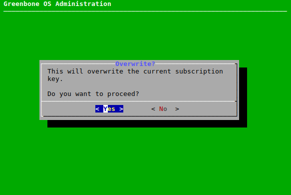
Fig. 6.45 Overwriting the current subscription key
Select Yes and press Enter.
Open the web browser and enter the displayed URL.
Click Browse…, select the subscription key and click Upload.
→ A message informs that the subscription key was uploaded successfully.
Press Enter to close the message.
Perform a feed update as described in Chapter 6.3.6.
Adding a Subscription Key Using the Editor
The key can be added using the editor as follows:
Select Setup and press Enter.
Select Feed and press Enter.
Select Key(Editor) and press Enter.
→ A message informs that the current subscription key will be overwritten (see Fig. 6.45).
Select Yes and press Enter.
→ The editor is opened.
Enter the content of the subscription key.
Note
It is important to enter the content of the key and not the name of the key (for example
gsf2022122017).The content of the key can be displayed with any text editor or under Linux using the program
less. If the content is opened with a text editor, care must be taken to not change anything.Press Ctrl + S to save the changes.
Press Ctrl + X to close the editor.
→ A message informs that the subscription key was uploaded successfully.
Press Enter to close the message.
Perform a feed update as described in Chapter 6.3.6.
6.2.7.2 Enabling or Disabling Synchronization
The automatic synchronization of the Greenbone Enterprise Feed can be disabled in case the appliance does not have any internet access and should not try to access the Greenbone services on the internet. The synchronization can be enabled again.
The synchronization can be enabled or disabled as follows:
Select Setup and press Enter.
Select Feed and press Enter.
Select Synchronisation and press Enter.
→ The synchronization is disabled.
The synchronization can be enabled by selecting Synchronisation and pressing Enter again.
Note
The time of the automatic feed synchronization can be set by changing the maintenance time (see Chapter 6.2.13).
6.2.7.3 Configuring the Synchronization Port
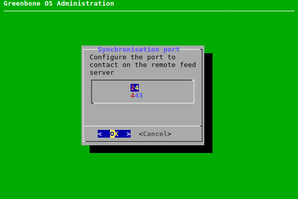
The Greenbone Enterprise Feed is provided by Greenbone on two different ports:
24/TCP
443/TCP
While port 24/TCP is the default port, many firewall setups do not allow traffic to this port on the internet. Therefore, changing the port to 443/TCP is possible since this port is most often allowed.
Note
Port 443/TCP is usually used by HTTPS traffic.
While the appliance uses this port, the actual traffic is not HTTPS but SSH since the appliance uses rsync embedded in SSH to retrieve the feed.
Firewalls using deep inspection and application awareness may still reject the traffic.
The port can be configured as follows:
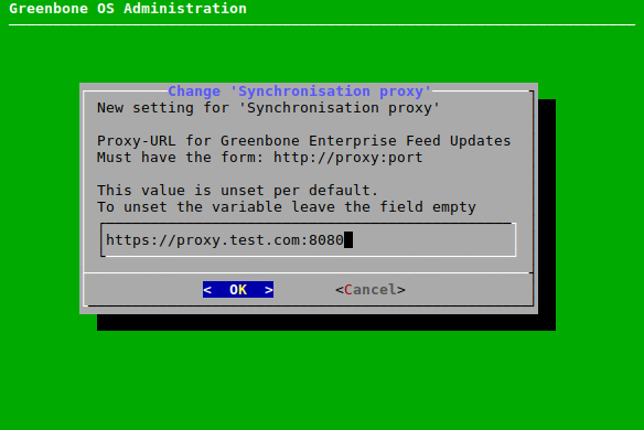
6.2.7.4 Setting the Synchronization Proxy
If a security policy does not allow for direct internet access, the appliance can use an HTTPS proxy service. This proxy must not inspect the SSL/TLS traffic but must support the CONNECT method. The traffic passing through the proxy is not HTTPS but SSH encapsulated in http-proxy.
The proxy can be set as follows:
6.2.7.5 Deleting the Greenbone Enterprise Feed Subscription Key
The subscription key can be removed. This is useful if an appliance has reached the end of its lifetime and is no longer in use. The cleanup ensures that there are no more licenses on the appliance. Without the subscription key, the appliance will only retrieve the Greenbone Community Feed.
Note
The model Greenbone Basic Appliance cannot be used with the Greenbone Community Feed.
The cleanup can be done as follows:
Select Setup and press Enter.
Select Feed and press Enter.
Select Cleanup and press Enter.
→ A warning informs that the synchronization with the Greenbone Enterprise Feed is no longer possible after the cleanup (see Fig. 6.48).
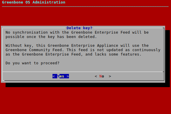
Fig. 6.48 Removing the subscription key
Select Yes and press Enter.
→ A message informs that the subscription key has been deleted.
Press Enter to close the message.
6.2.8 Configuring the Appliance as an Airgap Master/Sensor
The Airgap function allows an appliance that is not directly connected to the internet to obtain feed updates and GOS upgrades.
At least two appliances are required:
Airgap sensor: situated in a secured area and not connected to the internet
Airgap master: connected to the internet
Note
There is no technical limit to the number of Airgap sensors per Airgap master, however, performance limits of third-party systems, for example, the data diode server, may apply.
Airgap appliances may also be chained, which means that one Airgap sensor becomes the Airgap master for one or more other Airgap sensor(s).
Two options are available for the Airgap function:
Greenbone Airgap USB drive
Airgap FTP data diode server
The following appliance models can be configured for USB Airgap:
Greenbone Enterprise 400 and higher as Airgap USB master
Greenbone Enterprise 400 and higher as Airgap USB sensor
The following appliance models can be configured for FTP Airgap:
Greenbone Enterprise 400 and higher as Airgap FTP master
Greenbone Enterprise 150 and higher as Airgap FTP sensor
Greenbone Enterprise CENO and higher as Airgap FTP sensor
6.2.8.1 Using the Airgap USB Drive
The updates and upgrades are loaded from an appliance connected to the internet and copied to a USB drive. The USB drive can then can be used to update another appliance.
Note
The USB drive must be a specific Airgap USB drive provided by Greenbone. Contact the Greenbone Enterprise Support providing the customer number to request a respective Airgap USB drive.
By default, hardware appliances that can be used for USB Airgap are configured as Airgap USB sensors. If a suitable Airgap USB drive is connected to them, the Airgap USB sensor functionality will start. This means that the feed data will be copied over from the USB drive to the appliance and then a feed update will be performed on the appliance based on the copied data.
Configuring an appliance as an Airgap USB master disables the Airgap USB sensor functionality. Disabling the Airgap USB master functionality enables the Airgap USB sensor functionality again.
The USB drive can be checked for malware by a security gateway beforehand.
The data transfer using the Airgap USB drive is performed as follows:
In the GOS administration menu of the Airgap master, select Setup and press Enter.
Select Feed and press Enter.
Select Airgap Master and press Enter.
Select USB Master and press Enter (see Fig. 6.49).
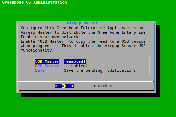
Fig. 6.49 Configuring the Airgap USB master
Select Save and press Enter.
Note
Configuring an appliance as an Airgap USB master disables the possibility to configure the appliance as an Airgap USB sensor at the same time.
Connect the Airgap USB drive to the Airgap master.
→ The data transfer starts automatically.
When the data transfer is finished, connect the Airgap USB drive to the Airgap sensor.
→ The data transfer starts automatically.
6.2.8.2 Using the Airgap FTP Server
The updates and upgrades can be provided via an FTP server operating as a data diode. A data diode is a unidirectional security gateway allowing the data flow in only one direction.
The FTP Airgap update is performed when a manual (see Chapter 6.3.6) or an automatic feed update at maintenance time is performed.
Note
The Airgap master must have enough time to upload the Airgap FTP feed to the FTP server. For slower connections, it may be advisable to set the maintenance time of the Airgap sensor at least three hours behind that of the Airgap master (see Chapter 6.2.9).
The configuration of an Airgap FTP setup is performed as follows:
In the GOS administration menu of the Airgap master, select Setup and press Enter.
Select Feed and press Enter.
Select Airgap Master and press Enter.
Select FTP Master and press Enter.
→ Additional menu options for the configuration of the FTP server are shown (see Fig. 6.50).
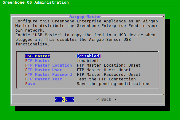
Fig. 6.50 Configuring the FTP server for the Airgap master
Select FTP Master Location and press Enter.
Enter the path of the FTP server in the input box and press Enter.
The required format for the path is
ftp://1.2.3.4orftp://path.to.ftpserver.Optionally, a port can be configured, for example
ftp://1.2.3.4:21.If no port is configured, the default FTP port 21 is used. If a port other than 21 should be used, it must be configured explicitly.
Select FTP Master User and press Enter.
Enter the user used for logging into the FTP server in the input box and press Enter.
Select FTP Master Password and press Enter.
Enter the password used for logging into the FTP server in the input box and press Enter.
Select FTP Master Test and press Enter.
→ It is tested whether a login with the entered information works.
Select Save and press Enter.
In the GOS administration menu of the Airgap sensor, select Setup and press Enter.
Select Feed and press Enter.
Select Airgap Sensor and press Enter.
Execute steps 5 to 12 in the GOS administration menu of the Airgap sensor with the same entries as for the Airgap master.
Note
The menu options have slightly different names than in the GOS administration menu of the Airgap master (see Fig. 6.51).
→ The data transfer starts during the next feed update.
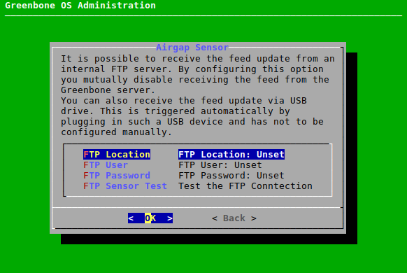
Fig. 6.51 Configuring the FTP server for the Airgap sensor
6.2.9 Configuring the Time Synchronization
To synchronize the appliance with central time servers, the appliance supports the Network Time Protocol (NTP). Up to four different NTP servers can be configured. The appliance will select the most suitable server. If a server fails, another server is used automatically.
Both IP addresses and DNS names are supported.
Note
Time zone and daylight saving time synchronization are not supported by NTP. The appliance’s time zone is always UTC±00:00.
The NTP settings can be configured as follows:
Select Setup and press Enter.
Select Timesync and press Enter.
Select Time synchronisation and press Enter.
→ The time synchronization is enabled.
Select the desired time server and press Enter (see Fig. 6.52).
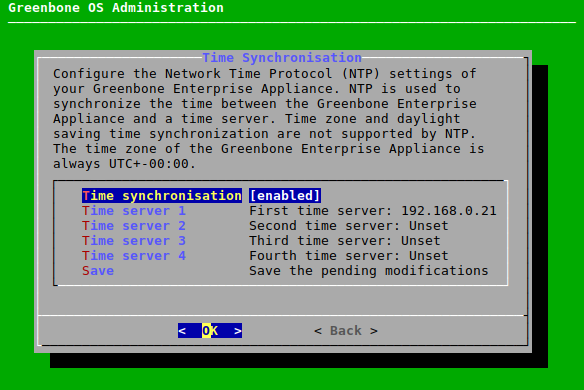
Fig. 6.52 Configuring the NTP settings
Enter the time server in the input box and press Enter.
→ A message informs that the changes must be saved.
Press Enter to close the message.
6.2.10 Selecting the Keyboard Layout
The appliance’s keyboard layout can be modified as follows:
Select Setup and press Enter.
Select Keyboard and press Enter.
→ All available keyboard layouts are displayed. The current layout has the annotation (selected) (see Fig. 6.53).
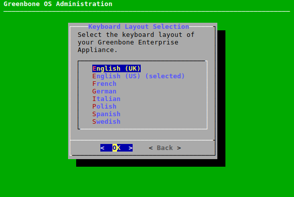
Fig. 6.53 Selecting the keyboard layout
Select the desired keyboard layout and press Enter.
→ A message asks to confirm the change.
Select Yes and press Enter.
→ A message informs that the layout was changed.
6.2.11 Configuring the E-Mails Settings
If reports of vulnerability scans or compliance audits should be delivered via e-mail, the appliance must first be connected to a server that acts as a mailhub. Such a server is also called a “mail relay”, “relay host” or “smart host”. By default, the appliance does not deliver e-mails directly to the internet, but only indirectly via the mailhub, through which they must then be forwarded to the recipients’ e-mail servers. The mailhub must support the Simple Mail Transfer Protocol (SMTP).
The appliance does not store e-mails in the event of delivery failure and no second delivery attempt is made.
Note
The appliance implements the Postfix mail transfer agent. The mailhub may need to be set up correctly to work with the appliance. Information about special configurations for this case can be found in the mailhub documentation.
In addition, any mailhub spam protection, such as the gray listing, must be disabled specifically for the appliance.
6.2.11.1 Configuring the Mailhub
The mailhub can be configured as follows:
Select Setup and press Enter.
Select Mail and press Enter.
Select Mail and press Enter.
Enter the mailhub’s URL in the input box (see Fig. 6.54).
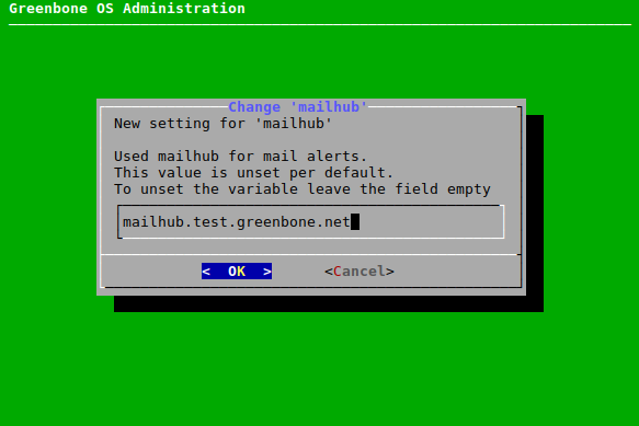
Fig. 6.54 Configuring the mailhub
Select OK and press Enter.
→ A message informs that the changes must be saved.
Press Enter to close the message.
Note
A port that is used for the mailhub can be configured if desired. However, a manual configuration is not necessary.
If no port is configured, the default ports for SMTP(S) are used automatically.
Select Mailhub Port and press Enter.
Enter the port in the input field and press Enter.
→ A message informs that the changes must be saved.
Press Enter to close the message.
6.2.11.2 Setting up SMTP
6.2.11.2.1 Configuring SMTP Authentication for the Mailhub
Note
The appliance only supports authentication via the SMTP-Auth extension. Authentication via NTLM is not supported.
Optionally, SMTP authentication can be configured for the used mailhub as follows:
Select Setup and press Enter.
Select Mail and press Enter.
Select SMTP Authentication Requirements and press Enter to enable SMTP authentication (see Fig. 6.55).
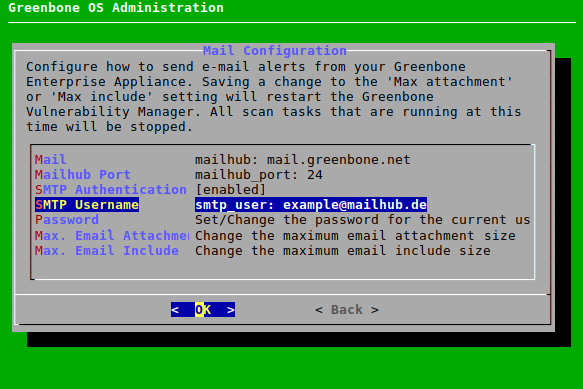
Fig. 6.55 Configuring SMTP authentication
Select SMTP Username and press Enter.
Enter the user name of the account used for authentication in the input field and press Enter.
→ A message informs that the changes must be saved.
Press Enter to close the message.
Select Password and press Enter.
Enter the password of the account used for authentication twice and press Tab.
Note
Passwords must not be longer than 128 characters.
Press Enter.
6.2.11.2.2 Enforcing the Usage of SMTPS
SMTPS can be enabled to always secure e-mail traffic using TLS.
Note
Only TLSv1, TLSv1.2 and TLSv1.3 are supported.
If SMTPS is enabled, the mailhub must also support SMTPS, otherwise the e-mail sending will fail.
Even if SMTPS is not enforced, GOS will automatically try to use encryption via STARTTLS. Only if the mailhub does not support STARTTLS, e-mail traffic is unencrypted.
SMTPS can be enforced as follows:
Select Setup and press Enter.
Select Mail and press Enter.
Select SMTP Enforce TLS and press Enter.
6.2.11.3 Configuring the Size of Included or Attached Reports
The maximum size (in bytes) of reports included in or attached to an e-mail (see Chapter 9.12) can be limited as follows:
Select Setup and press Enter.
Select Mail and press Enter.
Select Max. Email Attachment Size or Max. Email Include Size and press Enter.
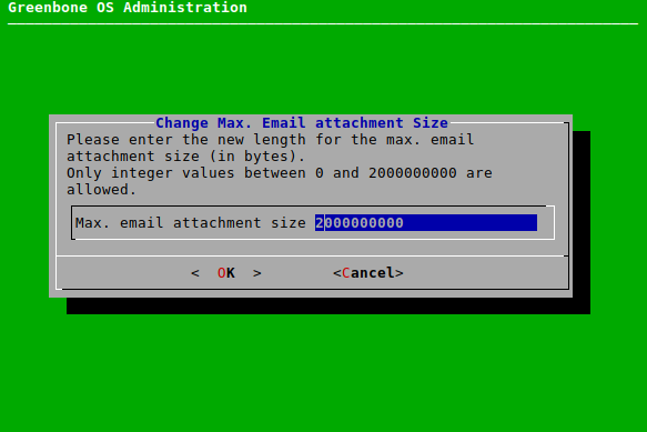
Fig. 6.56 Setting the maximum size of included or attached reports
→ A warning informs that changing the size requires a restart of the Greenbone Vulnerability Manager, which will cause all currently running scans to stop.
Enter the maximum size (in bytes) in the input box (see Fig. 6.56).
Select OK and press Enter.
→ A message informs that the changes must be saved.
Press Enter to close the message.
6.2.12 Configuring the Collection of Logs
The appliance supports the configuration of a central logging server for log collection. Either only the security-related logs or all system logs can be sent to a remote logging server.
The security-related logs contain only messages from the security and authentication logging facilities:
auth
authpriv
security
Additionally, the full logs contain the following facilities:
cron
daemon
ftp
kern
lp
lpr
ntp
mail
news
syslog
user
uucp
console
solaris-cron
local0 – local7
The appliance uses the syslog protocol. The central collection of logs allows central analysis, management and monitoring of the logs. Additionally, the logs are always stored locally as well.
A separate logging server can be configured for each type of log (security-related logs or all system logs).
UDP (default), TLS and TCP can be used for transmission.
TCP ensures log delivery even if packet loss occurs.
If a packet loss occurs during a transmission via UDP, the logs are lost.
TLS allows optional authentication of the sender via TLS. Only TLS 1.2 and TLS 1.3 are supported. This process is not RFC 5425 compliant.
Note
The time zone of the appliance (UTC±00:00) is used for the log time stamps unless adjusted on the syslog server.
6.2.12.1 Configuring the Logging Server
The logging server can be set up as follows:
Select Setup and press Enter.
Select Remote Syslog and press Enter.
Select Security Syslog and press Enter to enable security-related logs (see Fig. 6.57).
or
Select Full Syslog and press Enter to enable all system logs (see Fig. 6.57).
Note
Both logs can be enabled.
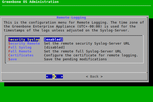
Fig. 6.57 Configuring the logs
Select Security Remote and press Enter to set the logging server URL for security-related logs.
or
Select Full Remote and press Enter to set the logging server URL for all system logs.
Enter the logging server URL including the desired protocol in the input box (see Fig. 6.58).
Note
If no port is specified, the default port 514 is used.
If no protocol is specified, UDP is used.
If TLS is used, an HTTPS certificate must exist (see Chapter 6.2.12.2).
→ A message informs that the changes must be saved.
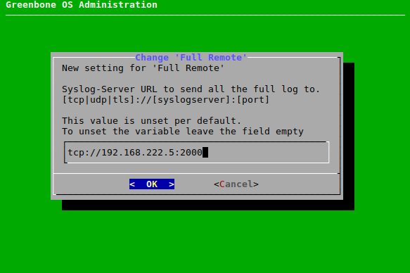
Fig. 6.58 Configuring the logging server
Press Enter to close the message.
6.2.12.2 Managing HTTPS Certificates for Logging
Creating a Certificate
HTTPS certificates for logging can be managed as follows:
Select Setup and press Enter.
Select Remote Syslog and press Enter.
Select Certificates and press Enter.
Select Generate and press Enter to generate a certificate.
→ A message informs that the current certificate and private key will be overwritten.
Confirm the message by selecting Yes and pressing Enter.
Provide the settings for the certificate (see Fig. 6.59), select OK and press Enter.
Note
It is valid to generate a certificate without a common name. However, a certificate should not be created without (a) Subject Alternative Name(s) (SAN).
If a common name is used, it should be the same as one of the SANs.
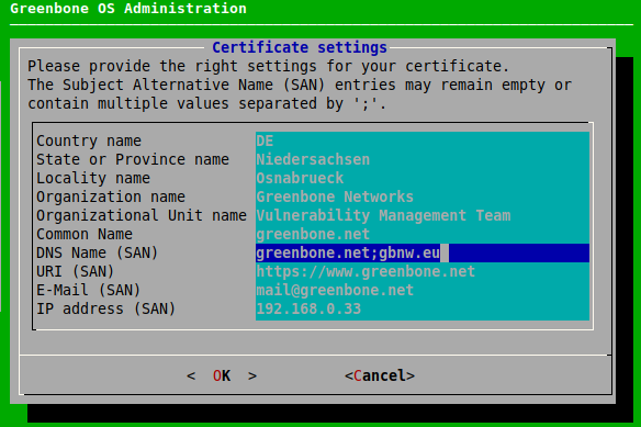
Fig. 6.59 Providing settings for the certificate
→ When the process is finished, a message informs that the certificate can be downloaded.
Press Enter to close the message.
Select Certificates and press Enter.
Select Download and press Enter.
Open the web browser and enter the displayed URL.
Download the file.
In the GOS administration menu, press Enter.
→ When the certificate is retrieved by the appliance, the GOS administration menu displays the fingerprint of the certificate for verification.
Check the fingerprint and confirm the certificate by pressing Enter.
Displaying the Current Certificate and the Fingerprints
The certificate and the according fingerprints can be displayed as follows:
Select Setup and press Enter.
Select Remote Syslog and press Enter.
Select Certificates and press Enter.
Select Show and press Enter to display the certificate.
Select Fingerprints and press Enter to display the fingerprint.
→ The following fingerprints of the currently active certificate are displayed:
SHA1
SHA256
6.2.13 Setting the Maintenance Time
During maintenance, the daily feed synchronization takes place. Additionally, an incremental backup is carried out (see Chapter 6.2.5).
Any time during the day can be selected, except for 10:00 a.m. to 1:00 p.m. UTC. During this time, Greenbone updates the feed and disables the synchronization services.
The default maintenance time is a random time between 3:00 a.m. and 5:00 a.m. UTC±00:00.
The maintenance time can be set as follows:
Select Setup and press Enter.
Select Time and press Enter.
Enter the desired maintenance time in the input box and press Enter (see Fig. 6.60).
Note
The time must be converted to UTC before entering it.
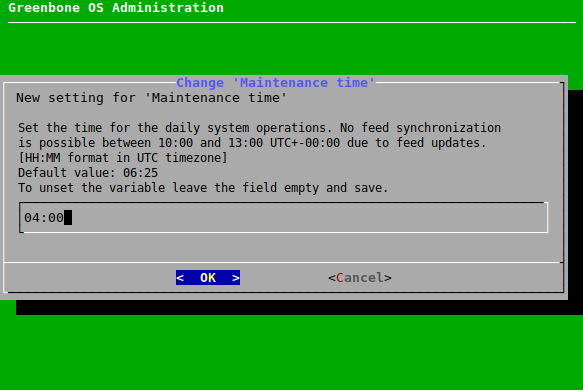
Fig. 6.60 Configuring the maintenance time
→ A message informs that the changes must be saved.
Press Enter to close the message.
6.3 Maintenance Menu
6.3.1 Performing a Self-Check
The self-check option checks the appliance setup. It displays wrong or missing configuration details that could prevent the appliance from functioning correctly. The following items are checked:
Network connection
DNS resolution
Feed reachability
Available updates
User configuration
The self-check is performed as follows:
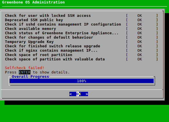
6.3.2 Performing and Restoring a Backup
Note
Periodic, automatic backups are configured in the menu Setup (see Chapter 6.2.5).
In addition to automatic backups, backups can also be performed manually. There are two different backup types with different use cases:
- Incremental backups
Only data that was changed since the last backup is saved.
If no backup is present, a full backup will be performed.
The incremental backup can be stored remotely on a server or locally on the appliance.
By default, the last 7 daily backups, the last 5 weekly backups and the last 12 monthly backups are stored. Backups older than one year will be deleted automatically.
Incremental backups are also started before GOS upgrades (see Chapter 6.3.4) if automatic backups are enabled (see Chapter 6.2.5).
- USB backups
First, a separate, full (temporary) backup is created on the appliance and then copied to the USB flash drive.
The temporary backup on the hard disk is deleted afterwards.
6.3.2.1 Incremental Backups
Depending on the backup location configured in Chapter 6.2.5, the incremental backups are stored remotely or locally.
The backups include user data (for example, tasks, reports, results) and system settings, meaning the GOS configuration.
6.3.2.1.1 Performing an Incremental Backup
A backup can be performed manually as follows:
Select Maintenance and press Enter.
Select Backup and press Enter.
Select Incremental Backup and press Enter (see Fig. 6.62).
→ A message informs that the backup was started in the background.
Tip
The currently running system operation can be displayed by selecting About and pressing Enter in the GOS administration menu.
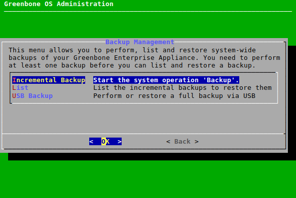
Fig. 6.62 Triggering a backup manually
6.3.2.1.2 Restoring an Incremental Backup
Note
Only backups created with the currently used GOS version or the previous GOS version can be restored. For GOS 22.04, only backups from GOS 21.04 or GOS 22.04 can be imported. If an older backup, for example from GOS 6 or GOS 20.08, should be imported, an appliance with a matching GOS version must be used.
Backups created with GOS versions newer than the currently used GOS version are also not supported. If a newer backup should be imported, an appliance with a matching GOS version must be used.
Only backups created with the same appliance model (see Chapter 3) can be restored.
It is checked whether the subscription keys of the backup and the appliance to which the backup should be restored are identical. If the keys do not match, a warning is displayed and the user must confirm that the key on the appliance should be overwritten. However, if a backup without a subscription key is restored, the key on the appliance is kept.
If a new backup password is configured (see Chapter 6.2.5.2), and a backup is restored that was created with a previous password, the previous password is not restored. The appliance will always use the newest backup password that was configured.
If there are any questions, contact the Greenbone Enterprise Support.
A backup can be restored as follows:
Select Maintenance and press Enter.
Select Backup and press Enter.
Select List and press Enter.
Select the desired backup and press Enter.
Select Yes and press Enter if both user data and system settings should be uploaded.
or
Select No and press Enter if only user data should be uploaded.
Note
The system settings include all GOS configurations, for example the network settings.
The user data includes all vulnerability scanning and management information.
→ A warning informs that all local settings are lost if the backup is restored (see Fig. 6.63).
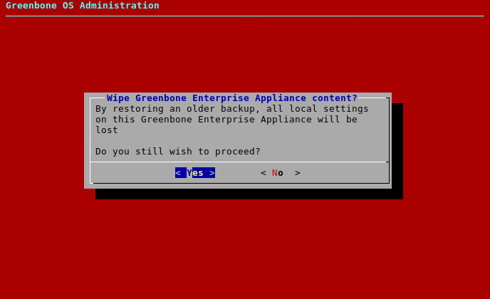
Fig. 6.63 Restoring a backup
Confirm the message by selecting Yes and pressing Enter.
→ A message informs that the restoration was started in the background.
Tip
The currently running system operation can be displayed by selecting About and pressing Enter in the GOS administration menu.
6.3.2.2 USB Backups
6.3.2.2.1 Performing a USB Backup
Backups can be performed on a USB flash drive as follows:
Connect a USB drive to the appliance.
Select Maintenance and press Enter.
Select Backup and press Enter.
Select USB Backup and press Enter.
→ If the used USB drive is not formatted for use as a GOS backup device yet, a message asks whether the USB drive should be formatted.
If the USB drive is formatted for use as a GOS backup device already, no message is displayed. Continue with step 7.
Select Yes and press Enter.
→ A warning informs that the stored data is erased if the drive is formatted.
Select Yes and press Enter.
→ The USB drive is formatted for use as a GOS USB backup device.
Select Backup and press Enter (see Fig. 6.64).
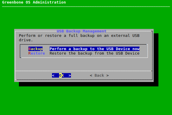
Fig. 6.64 Performing a backup using a USB drive
→ A message asks to confirm the backup.
Select Yes and press Enter.
→ A message informs that the backup was started in the background.
Tip
The currently running system operation can be displayed by selecting About and pressing Enter in the GOS administration menu.
6.3.2.2.2 Restoring a USB Backup
Note
Only backups created with the currently used GOS version or the previous GOS version can be restored. For GOS 22.04, only backups from GOS 21.04 or GOS 22.04 can be imported. If an older backup, for example from GOS 6 or GOS 20.08, should be imported, an appliance with a matching GOS version must be used.
Backups created with GOS versions newer than the currently used GOS version are also not supported. If a newer backup should be imported, an appliance with a matching GOS version must be used.
Only backups created with the same appliance model (see Chapter 3) can be restored.
It is checked whether the subscription keys of the backup and the appliance to which the backup should be restored are identical. If the keys do not match, a warning is displayed and the user must confirm that the key on the appliance should be overwritten. However, if a backup without a subscription key is restored, the key on the appliance is kept.
If a new backup password is configured (see Chapter 6.2.5.2), and a backup is restored that was created with a previous password, the previous password is not restored. The appliance will always use the newest backup password that was configured.
If there are any questions, contact the Greenbone Enterprise Support.
Backups can be restored from a USB drive as follows:
Connect the USB drive containing the desired GOS backup to the appliance.
Note
In case of problems, another USB drive or another USB port on the appliance should be tried.
Select Maintenance and press Enter.
Select Backup and press Enter.
Select USB Backup and press Enter.
Select Restore and press Enter (see Fig. 6.64).
Select Yes and press Enter if both user data and system settings should be uploaded.
or
Select No and press Enter if only user data should be uploaded.
Note
The system settings include all GOS configurations, for example the network settings.
The user data includes all vulnerability scanning and management information.
→ A warning informs that all local settings are lost if the backup is restored (see Fig. 6.65).
Fig. 6.65 Restoring a backup
Confirm the message by selecting Yes and pressing Enter.
→ A message informs that the restoration was started in the background.
Tip
The currently running system operation can be displayed by selecting About and pressing Enter in the GOS administration menu.
6.3.3 Copying Data and Settings to Another Appliance with Beaming
The current state of an appliance can be copied to another appliance. This includes user data (for example, tasks, reports, results) and system settings (meaning the GOS configuration).
On the receiving appliance, the user can decide whether to import only the user data, or both the user data and the system settings.
Note
Only beaming images created with the currently used GOS version or the previous GOS version can be restored. For GOS 22.04, only beaming images from GOS 21.04 or GOS 22.04 can be imported. If an older beaming image, for example from GOS 20.08, should be imported, an appliance with a matching GOS version must be used.
It is only possible to import a beaming image to an appliance if the release information, which means that the list of available GOS upgrades, on the corresponding appliance is up-to-date. To ensure this, a current Greenbone Enterprise Feed should be downloaded.
Beaming images created with GOS versions newer than the currently used GOS version are also not supported. If a newer beaming image should be imported, an appliance with a matching GOS version must be used.
The following restrictions apply regarding the models between which beaming is possible:
Beaming is only allowed to an appliance of the same or of a higher class (see Chapter 3).
Beaming from a sensor-only appliance (Greenbone Enterprise 35 and Greenbone Enterprise 25V) is only supported to another sensor-only appliance. Beaming to any other appliance class is not supported, not even the beaming of settings.
Beaming to a Greenbone Free is not supported.
Only data or settings of features which are available on the receiving appliance can be beamed. The model overview provides information about whether a specific feature is available on the used appliance model.
It is checked whether the subscription keys of the beaming image and the appliance to which the beaming image should be restored are identical. If the keys do not match, a warning is displayed and the user must confirm that the key on the appliance should be overwritten. However, if a beaming image without a subscription key is restored, the key on the appliance is kept.
If there are any questions, contact the Greenbone Enterprise Support.
6.3.3.1 Beaming Directly from Another Appliance
The beaming image can be created and copied directly as follows:
Note
Appliance A = Sending appliance
Appliance B = Receiving appliance
In the GOS administration menu of Appliance A, select Maintenance and press Enter.
Select Beaming and press Enter.
Select Download and press Enter (see Fig. 6.66).
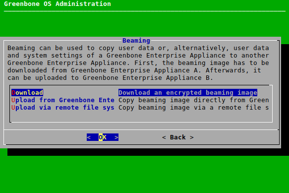
Fig. 6.66 Downloading a beaming image
→ A message informs that the beaming image creation was started in the background.
Tip
The currently running system operation can be displayed by selecting About and pressing Enter in the GOS administration menu.
When the creation is finished, a message informs that a password that must be noted will be shown.
Press Enter.
Note the password. It is needed in step 13.
Press q to close the editor.
Important
Do not close the message displaying the URL.
In the GOS administration menu of Appliance B, select Maintenance and press Enter.
Select Beaming and press Enter.
Select Upload from Greenbone Enterprise Appliance A and press Enter.
Enter the URL displayed in the GOS administration menu of Appliance A in the input box and press Enter.
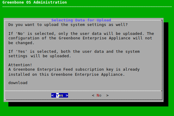
Fig. 6.67 Selecting the data and settings for uploading
Select Yes and press Enter if both user data and system settings should be uploaded.
or
Select No and press Enter if only user data should be uploaded.
→ A warning asks to confirm the process.
Select Yes and press Enter.
Enter the password from step 5 in the input box and press Enter (see Fig. 6.68).
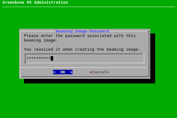
Fig. 6.68 Entering the password for the beaming image
→ A message informs that the beaming image upload was started in the background.
Tip
The currently running system operation can be displayed by selecting About and pressing Enter in the GOS administration menu.
When the upload is finished, a message is displayed.
Press Enter.
6.3.3.2 Beaming via Remote File System
A beaming image can be created, downloaded, stored, and imported later via a remote file system as follows:
Note
Appliance A = Sending appliance
Appliance B = Receiving appliance
In the GOS administration menu of Appliance A, select Maintenance and press Enter.
Select Beaming and press Enter.
Select Download and press Enter (see Fig. 6.69).
Fig. 6.69 Downloading a beaming image
→ A message informs that the beaming image creation was started in the background.
Tip
The currently running system operation can be displayed by selecting About and pressing Enter in the GOS administration menu.
When the creation is finished, a message informs that a password that must be noted will be shown.
Press Enter.
Note the password. It is needed in step 16.
Press q to close the editor.
Open the web browser and enter the displayed URL.
Note
This URL is valid for one download only. If the beaming image has been downloaded once, and the link is opened another time in a web browser, it will be displayed that no connection is possible.
→ The beaming image is downloaded automatically as a GSMB file.
In the GOS administration menu of Appliance B, select Maintenance and press Enter.
Select Beaming and press Enter.
Select Upload via remote file system and press Enter.
Open the web browser and enter the displayed URL.
Click Browse…, select the GSMB file and click Upload.
Fig. 6.70 Selecting the data and settings for uploading
Select Yes and press Enter if both user data and system settings should be uploaded.
or
Select No and press Enter if only user data should be uploaded.
→ A warning asks to confirm the process.
Select Yes and press Enter.
Enter the password from step 5 in the input box and press Enter (see Fig. 6.71).
Fig. 6.71 Entering the password for the beaming image
→ A message informs that the beaming image upload was started in the background.
Tip
The currently running system operation can be displayed by selecting About and pressing Enter in the GOS administration menu.
When the upload is finished, a message is displayed.
Press Enter.
6.3.4 Performing a GOS Upgrade
During the daily feed update at maintenance time (see Chapter 6.2.13), the appliance also downloads new GOS upgrades, if available. While the upgrades are downloaded automatically, they must be installed manually.
If enabled, an incremental backup (see Chapter 6.2.5) is carried out before the GOS upgrade. This happens on a per-appliance basis, which means that for master-sensor setups, the master only triggers the GOS upgrade on the sensor and the sensor then triggers the backup itself.
Note
Because the upgrades can interrupt running scan tasks, they must be scheduled carefully.
Upgrades can be installed manually as follows:
Select Maintenance and press Enter.
Select Upgrade and press Enter.
Select Upgrade and press Enter to install an upgrade.
or
Select Switch Release and press Enter to switch to a new release.
→ A message informs that the upgrade was started in the background.
Tip
The currently running system operation can be displayed by selecting About and pressing Enter in the GOS administration menu.
Note
If errors occur when using the web interface after a GOS upgrade, the browser or page cache must be cleared. Clearing the browser cache can be done in the options of the used browser. The page cache of a page of the web interface can be emptied by pressing
CtrlandF5. Clearing the page cache must be done for every single page, while clearing the browser cache is global and applies to all pages.It is possible that a GOS upgrade changes the functionality available via the GOS administration menu. This changed functionality will only be available after reloading the GOS administration menu. Therefore, it is recommended to log out of the GOS administration menu and log back in after the GOS upgrade.
Occasionally, a reboot of the appliance is required as well (see Chapter 6.3.9.1). The self-check displays a corresponding note if this is the case (see Chapter 6.3.1).
Note
By default, a successful GOS upgrade on the master will also start a GOS upgrade on the connected sensors. However, an upgrade can also be installed manually on the sensors (see Chapter 6.3.5).
6.3.5 Performing a GOS Upgrade on Sensors
A GOS upgrade on a sensor can be installed as follows:
Select Maintenance and press Enter.
Select Upgrade and press Enter.
Select Sensors and press Enter.
Select the desired sensor and press Space.
→ The sensor is marked with *. Multiple sensors can be selected at the same time.
Sensors that are not ready for an upgrade are labelled accordingly.
Press Enter.
→ A message informs that the upgrade was started in the background.
Tip
The currently running system operation can be displayed by selecting About and pressing Enter in the GOS administration menu.
6.3.6 Performing a Feed Update
By default, the appliance tries to download feed updates and GOS upgrades daily at its maintenance time (see Chapter 6.2.13).
Additionally, a feed update can be triggered manually as follows:
Select Maintenance and press Enter.
Select Feed and press Enter.
Select Update and press Enter (see Fig. 6.72).
→ A message informs that the feed update was started in the background.
Tip
The currently running system operation can be displayed by selecting About and pressing Enter in the GOS administration menu.
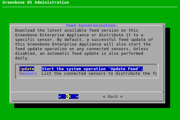
Fig. 6.72 Triggering a feed update manually
Note
By default, a successful feed update on the master will also start a feed update on the connected sensors. However, a feed update can also be pushed manually to the sensors (see Chapter 6.3.7).
6.3.7 Performing a Feed Update on Sensors
A feed update can be pushed to a sensor as follows:
Select Maintenance and press Enter.
Select Feed and press Enter.
Select Sensors and press Enter.
Select the desired sensor and press Enter (see Fig. 6.73).
→ A message informs that the feed update was started in the background.
Tip
The currently running system operation can be displayed by selecting About and pressing Enter in the GOS administration menu.
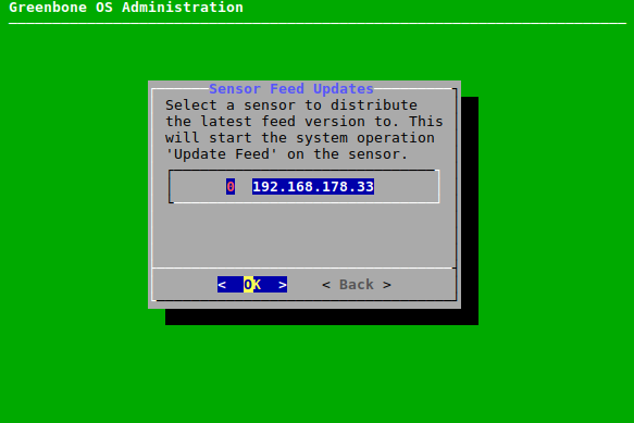
Fig. 6.73 Selecting the sensor
6.3.8 Upgrading the Flash Partition
The flash partition is used to perform factory resets of the appliance. To simplify factory resets, it should be upgraded to the latest GOS version regularly.
Note
Make sure that the appliance itself is able to connect to the Greenbone Feed Server.
It is not possible to upgrade the flash partition of sensors via the master.
The flash partition can be upgraded as follows:
Upgrade the appliance to the latest GOS version (see Chapter 6.3.4).
Select Maintenance and press Enter.
Select Flash and press Enter.
Select Download and press Enter (see Fig. 6.74).
→ The latest flash image is downloaded.
Tip
The download status can be monitored in the live logs (Advanced > Logs > Live, see Chapter 6.4.1).
When the download is finished, select Write and press Enter (see Fig. 6.74) .
→ The image is written to the flash partition. The process may take up to 20 minutes.
Tip
The currently running system operation can be displayed by selecting About and pressing Enter in the GOS administration menu.
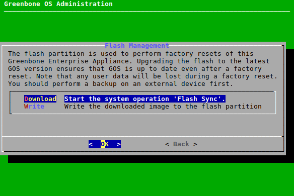
Fig. 6.74 Upgrading the flash partition
6.3.9 Shutting down and Rebooting the Appliance
Note
The appliance should not be turned off via the power switch.
Instead, the appliance should be shut down and rebooted via the GOS administration menu. This ensures that the mandatory cleanup processes are executed during shutdown and reboot.
6.3.9.1 Rebooting the Appliance
The appliance is rebooted as follows:
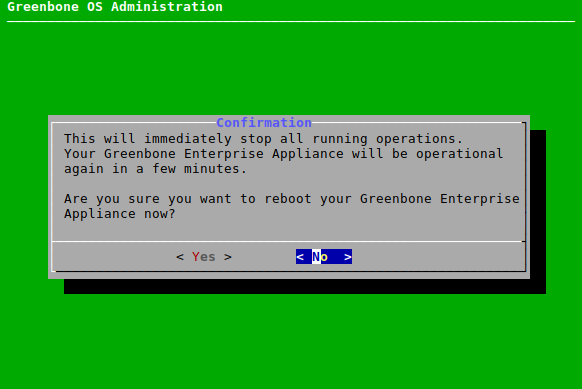
6.3.9.2 Shutting down the Appliance
The appliance is shut down as follows:
Select Maintenance and press Enter.
Select Power and press Enter.
Select Shutdown and press Enter.
→ A message asks to confirm the shutdown (see Fig. 6.76).
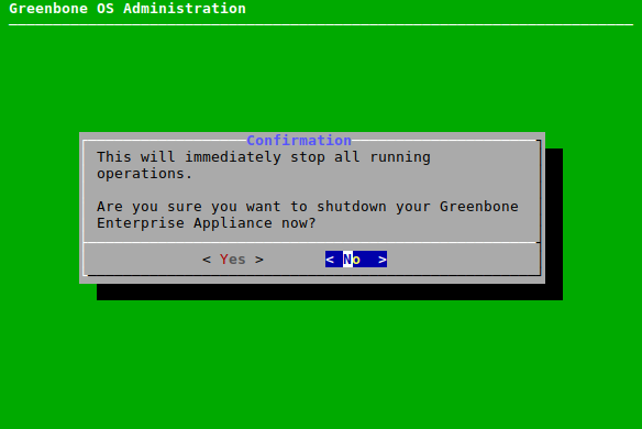
Fig. 6.76 Shutting down the appliance
Select Yes and press Enter.
→ The appliance will shutdown. The shutdown process may take up to several minutes.
6.3.10 Extending the Disk Volumes
The partition layout can be applied as follows:
Note
The menu option is only displayed for affected appliance models and disappears after using it.
For more information see Chapter 5.1.6.
Select Maintenance and press Enter.
Select Extend disk volumes and press Enter.
→ A warning asks to confirm the process.
Select Continue and press Enter.
→ The disk volumes are extended. The menu option Extend disk volumes is not displayed anymore.
6.4 Advanced Menu
6.4.1 Displaying the Log Files of the Appliance
The log files of the appliance can be displayed as follows:
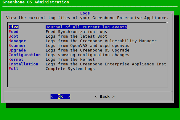
6.4.2 Performing Advanced Administrative Work
6.4.2.1 Managing the Superuser Account
When the shell is accessed, a Linux command line is displayed with the unprivileged user admin (see Chapter 6.4.2.3). Any Debian GNU/Linux command can be executed, however some commands may be limited to the privileged user root.
Note
The privileged account root (superuser) should only be used in consultation with the Greenbone Enterprise Support.
If changes are made without consultation, the claim for support by the Greenbone Enterprise Support expires.
To obtain root privileges on the appliance, the command su - must be entered in the shell.
The use of su - to switch from the admin user to the root user is disabled by default.
The superuser must be enabled and provided with a password as follows:
Select Advanced and press Enter.
Select Support and press Enter.
Select Superuser and press Enter.
Select Superuser State and press Enter (see Fig. 6.78).
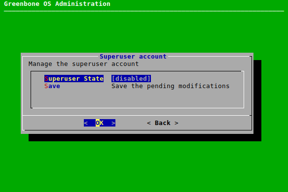
Fig. 6.78 Enabling the superuser
→ A warning informs that root privileges should only be obtained by exception and while consulting the Greenbone Enterprise Support.
Select Yes and press Enter.
→ A message informs that the changes must be saved.
Press Enter to close the message.
Select Password and press Enter.
Enter the password twice, select OK and press Enter (see Fig. 6.79).

Fig. 6.79 Defining the superuser password
6.4.2.2 Generating and Downloading a Support Package
Sometimes the Greenbone Enterprise Support needs additional information to troubleshoot and support customers. The required data is collected in the form of an (encrypted) support package that contains all configuration data of the appliance.
The package can be encrypted using the Greenbone Enterprise Support GPG public key. The support package is stored on the appliance.
A support package can be created as follows:
Select Advanced and press Enter.
Select Support and press Enter.
Select Support Package and press Enter.
→ A message asks to confirm the generation of the support package.
Select Yes and press Enter.
→ A message asks whether the support package should be encrypted (see Fig. 6.80).
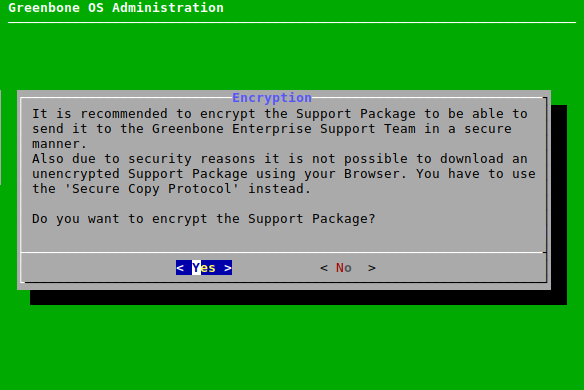
Fig. 6.80 Downloading a support package
Select Yes and press Enter to encrypt the support package.
or
Select No and press Enter to not encrypt the support package.
If an encrypted support package was chosen, open the web browser, enter the displayed URL and download the GPG file (encrypted ZIP folder).
or
Note
If the support package is not encrypted, the download must be done via the Secure Copy Protocol (SCP). To do so, SSH must be enabled first (see Chapter 6.2.4.4).
If an unencrypted support package was chosen, enter the displayed command using SCP (see Fig. 6.81) and download the support package (ZIP folder).
Note
The “.” at the end can be replaced by a path. If the “.” is kept, the current folder will be chosen.
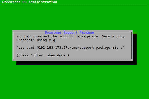
Fig. 6.81 Downloading an unencrypted support package
Send the ZIP folder to the Greenbone Enterprise Support.
On Microsoft Windows systems, the support package can be downloaded using either pscp, a command line tool included in PuTTY, or smarTTY, a graphical tool implementing SCP.
6.4.2.3 Accessing the Shell
Shell access is not required for any administrative work but can be requested by the Greenbone Enterprise Support for diagnostics and support.
The shell can be accessed as follows:
Select Advanced and press Enter.
Select Support and press Enter.
Select Shell and press Enter.
→ A warning informs that the shell level is undocumented and should not be used for administrative settings (see Fig. 6.82).
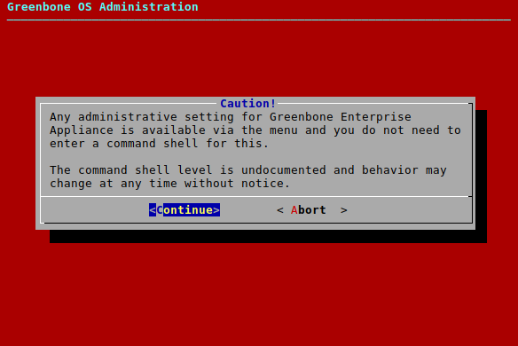
Fig. 6.82 Warning when accessing the shell
Select Continue and press Enter.
→ A Linux shell is opened with the unprivileged user admin (see Fig. 6.83).
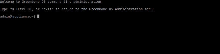
Fig. 6.83 Accessing the local shell
Note
Accessing as root requires enabling the superuser and setting a password (see Chapter 6.4.2.1). Afterwards, switching to root is possible using the command
su -.Enter
exitor press Ctrl + D to quit the shell.
6.4.3 Displaying the Greenbone Enterprise Feed Subscription Key
The subscription key (see Chapter 6.2.7.1) can be displayed as follows:
Select Advanced and press Enter.
Select Subscription and press Enter (see Fig. 6.84).
→ The subscription key is displayed in a viewer.
Press q to quit the viewer.
6.4.4 Displaying the Copyright and License Information
The copyright file can be displayed as follows:
Select Advanced and press Enter.
Select Copyright and Licenses and press Enter (see Fig. 6.84).
→ The copyright file is displayed in a viewer.
Press q to quit the viewer.
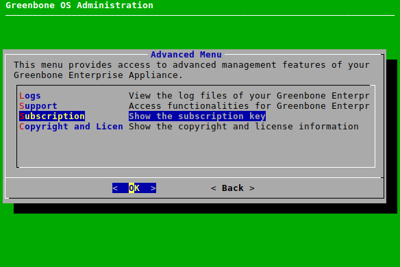
Fig. 6.84 Displaying the subscription key or the copyright file
6.5 Displaying Information about the Appliance
Information about the appliance can be displayed by selecting About and pressing Enter.
The following information is displayed:
Appliance model
GOS version
Feed version
Name of the subscription key
IP address of the web interface
Configured sensors
Currently running system operations
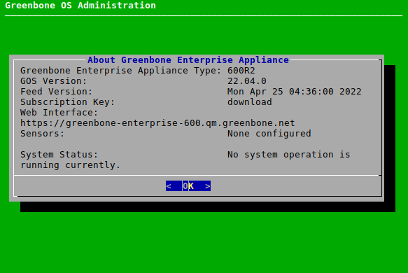
Fig. 6.85 Displaying information about the appliance