4 Setting up OPENVAS SCAN
4.1 Setup Requirements
4.1.1 OPENVAS SCAN G90 and OPENVAS SCAN 6500/5400
OPENVAS SCAN G90, OPENVAS SCAN 6500 and OPENVAS SCAN 5400 are 19-inch mountable and require two rack units (RU). Rack holders for the installation in a 19-inch rack are supplied.
For cabling, OPENVAS SCAN G90, OPENVAS SCAN 6500 and OPENVAS SCAN 5400 have corresponding connectors at the front and back:
- Front
1 RJ45 console port, suitable cable is enclosed
1 Mini-USB console port
2 USB 3.0 ports
2 Gigabit Ethernet RJ45 ports, for management
1 module with 8 Gigabit Ethernet RJ45 ports
Note
Additional network modules must be purchased separately. A maximum of four network modules can be installed in total. The network modules can contain either up to eight Gigabit Ethernet RJ45 ports, eight Gigabit Ethernet SFP ports, or two 10 Gigabit Ethernet SFP+ ports.
- Back
1 VGA port
2 power supplies
The installation requires either a monitor and a keyboard or a serial console connection and a terminal application.
4.1.2 OPENVAS SCAN G30/G10 and OPENVAS SCAN 650/600/450/400
OPENVAS SCAN G30, OPENVAS SCAN G10, OPENVAS SCAN 650, OPENVAS SCAN 600, OPENVAS SCAN 450 and OPENVAS SCAN 400 are 19-inch mountable and require one rack unit (RU). Rack holders for the installation in a 19-inch rack are supplied.
For cabling, OPENVAS SCAN G30, OPENVAS SCAN G10, OPENVAS SCAN 650, OPENVAS SCAN 600, OPENVAS SCAN 450 and OPENVAS SCAN 400 have corresponding connectors at the front and back:
- Front
1 RJ45 console port, suitable cable is enclosed
2 USB 3.0 ports
8 Gigabit Ethernet RJ45 ports
2 10 Gigabit Ethernet SFP+ ports
1 HDMI port
- Back
1 power supply
The installation requires either a monitor and a keyboard or a serial console connection and a terminal application.
4.1.3 OPENVAS SCAN 150
OPENVAS SCAN 150 is 19-inch mountable and requires one rack unit (RU). The optional RACKMOUNT150 kit provides the rack holders for installing the appliance in a 19-inch rack.
For stand-alone appliances, four self-sticking rubber pads must be mounted on the corresponding bottom side embossments.
For cabling, OPENVAS SCAN 150 has corresponding connectors at the front and back:
- Front
1 RJ45 console port, suitable cable is enclosed
2 USB 3.0 ports
8 Gigabit Ethernet RJ45 ports
2 10 Gigabit Ethernet SFP+ ports
1 HDMI port
- Back
1 power supply
The installation requires either a monitor and a keyboard or a serial console connection and a terminal application.
4.1.4 OPENVAS SCAN 35
OPENVAS SCAN 35 is 19-inch mountable and requires one rack unit (RU). The optional RACKMOUNT35 kit provides the rack holders for installing the appliance in a 19-inch rack.
For stand-alone appliances, four self-sticking rubber pads must be mounted on the corresponding bottom side embossments.
For cabling, OPENVAS SCAN 35 has corresponding connectors at the front and back:
- Front
1 RJ45 console port, suitable cable is enclosed
2 USB 3.0 ports
4 Gigabit Ethernet RJ45 ports
1 HDMI port
- Back
1 power supply
The installation requires either a monitor and a keyboard or a serial console connection and a terminal application.
4.1.5 OPENVAS SCAN VIRTUAL
This section lists the requirements for successfully deploying OPENVAS SCAN VIRTUAL. All requirements must be met.
The virtual appliance requires the following resources:
2 virtual CPUs (minimum, can be increased)
12 GB RAM (minimum, can be increased)
500 GB virtual hard disk
The following hypervisors are officially supported for running OPENVAS SCAN VIRTUAL:
Microsoft Hyper-V: Server 2016 (generation 2 virtual machine, VM configuration version 8.0 or higher)
VMware vSphere Hypervisor (ESXi), version 7.0 or higher
Huawei FusionCompute, version 8.0
Proxmox Virtual Environment (VE), version 8.0 or higher
Nutanix AHV, version 6.8 or higher
For Microsoft Hyper-V, OPENVAS SCAN VIRTUAL is delivered as a generation 2 virtual machine.
The required booting mode is the EFI/UEFI boot mode.
4.1.6 OPENVAS SCAN EXA/PETA/TERA/DECA
This section lists the requirements for successfully deploying OPENVAS SCAN EXA, OPENVAS SCAN PETA, OPENVAS SCAN TERA or OPENVAS SCAN DECA. All requirements must be met.
The virtual appliances require and are limited to the following resources:
OPENVAS SCAN EXA
12 virtual CPUs
24 GB RAM
500 GB virtual hard disk
OPENVAS SCAN PETA
8 virtual CPUs
16 GB RAM
500 GB virtual hard disk
OPENVAS SCAN TERA
6 virtual CPUs
14 GB RAM
500 GB virtual hard disk
OPENVAS SCAN DECA
4 virtual CPUs
14 GB RAM
500 GB virtual hard disk
The following hypervisors are officially supported for running OPENVAS SCAN EXA/PETA/TERA/DECA:
Microsoft Hyper-V: Server 2016 (generation 2 virtual machine, VM configuration version 8.0 or higher)
VMware vSphere Hypervisor (ESXi), version 7.0 or higher
Huawei FusionCompute, version 8.0
Proxmox Virtual Environment (VE), version 8.0 or higher
For Microsoft Hyper-V, OPENVAS SCAN EXA/PETA/TERA/DECA is delivered as a generation 2 virtual machine.
The required booting mode is the EFI/UEFI boot mode.
4.1.7 OPENVAS SCAN CENO
This section lists the requirements for successfully deploying OPENVAS SCAN CENO. All requirements must be met.
The virtual appliance requires and is limited to the following resources:
2 virtual CPUs
12 GB RAM
500 GB virtual hard disk
The following hypervisors are officially supported for running OPENVAS SCAN CENO:
Microsoft Hyper-V: Server 2016 (generation 2 virtual machine, VM configuration version 8.0 or higher)
VMware vSphere Hypervisor (ESXi), version 7.0 or higher
Proxmox Virtual Environment (VE), version 8.0 or higher
For Microsoft Hyper-V, OPENVAS SCAN CENO is delivered as a generation 2 virtual machine.
The required booting mode is the EFI/UEFI boot mode.
4.1.8 OPENVAS SCAN 25V
This section lists the requirements for successfully deploying OPENVAS SCAN 25V. All requirements must be met.
The virtual appliance requires and is limited to the following resources:
2 virtual CPUs
8 GB RAM
500 GB virtual hard disk
The following hypervisors are officially supported for running OPENVAS SCAN 25V:
Microsoft Hyper-V: Server 2016 (generation 2 virtual machine, VM configuration version 8.0 or higher)
VMware vSphere Hypervisor (ESXi), version 7.0 or higher
Huawei FusionCompute, version 8.0
Proxmox Virtual Environment (VE), version 8.0 or higher
For Microsoft Hyper-V, OPENVAS SCAN 25V is delivered as a generation 2 virtual machine.
The required booting mode is the EFI/UEFI boot mode.
4.1.9 OPENVAS BASIC
This section lists the requirements for successfully deploying OPENVAS BASIC. All requirements must be met.
The virtual appliance requires and is limited to the following resources:
2 virtual CPUs
12 GB RAM
500 GB virtual hard disk
The following hypervisors are officially supported for running OPENVAS BASIC:
Microsoft Hyper-V: Server 2016 (generation 2 virtual machine, VM configuration version 8.0 or higher)
VMware vSphere Hypervisor (ESXi), version 7.0 or higher
VMware Workstation Pro, version 17.0 or higher
Oracle VirtualBox, version 7.0 or higher
Huawei FusionCompute, version 8.0
Proxmox Virtual Environment (VE), version 8.0 or higher
The required booting mode is the EFI/UEFI boot mode.
Note
The following steps are mandatory for OPENVAS BASIC, otherwise no vulnerability scans can be performed:
Entering or uploading an OPENVAS ENTERPRISE FEED subscription key (see Chapter 4.4.4)
Downloading the OPENVAS ENTERPRISE FEED (see Chapter 4.4.5)
An OPENVAS ENTERPRISE FEED subscription key is provided with the order of OPENVAS BASIC. If no key was received, contact sales@greenbone.net.
4.1.10 OPENVAS SCAN ONE
This section lists the requirements for successfully deploying OPENVAS SCAN ONE. All requirements must be met.
The virtual appliance requires and is limited to the following resources:
2 virtual CPUs
12 GB RAM
500 GB virtual hard disk
The following hypervisors are officially supported for running OPENVAS SCAN ONE:
Oracle VirtualBox, version 7.0 or higher
VMware Workstation Pro, version 17.0 or higher
Proxmox Virtual Environment (VE), version 8.0 or higher
The required booting mode is the EFI/UEFI boot mode.
4.2 Setting up a Hardware Appliance
Note
The requirements for installing the appliance can be found in Chapter 4.1.
4.2.1 Utilizing the Serial Port
The enclosed console cable is used for utilizing the serial port.
To access the serial port, a terminal application is required. The application must be configured to a speed of 9600 bits/s.
Under Linux, the command screen can be used in the command line to access the serial port.
The device providing the serial port must be passed as a parameter:
screen /dev/ttyS0  #(for serial port)
screen /dev/ttyUSB0 #(for USB adapter)
Tip
After starting screen, it may be necessary to press Enter several times to see a command prompt.
To close the serial connection, press Ctrl + a and immediately afterwards \.
In Microsoft Windows, PuTTY can be used. After starting it, the options as shown in Fig. 4.1 and the appropriate serial port must be selected.
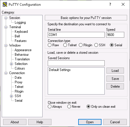
Fig. 4.1 Setting up the serial port in PuTTY
4.2.2 Starting the Appliance
Once the appliance is fully wired, connected via the console cable, and the terminal application (PuTTY, screen or similar) is configured, the appliance can be started.
The appliance will boot and after a short time – depending on the exact model – the login prompt is shown. The default login information is:
User:
adminPassword:
admin
Note
During the first setup, this password should be changed (see Chapter 6.2.1.1).
4.3 Setting up a Virtual Appliance
Note
The requirements for installing the appliance can be found in Chapter 4.1.
4.3.1 Verification of Integrity
Note
The integrity of the virtual appliance can be verified. On request, the Greenbone Support Team provides an integrity checksum.
To request the checksum, contact the Greenbone Support Team and provide the subscription key name.
The integrity checksum can be provided by phone or via support portal.
The local verification of the checksum depends on the host operating system.
On Linux systems, the following command for calculating the checksum can be used:
sha256sum <file>
Note
Replace <file> with the name of the appliance’s OVA file.
On Microsoft Windows systems, the following command for calculating the checksum can be used in the Windows PowerShell:
Get-Filehash 'C:\<path>\<file>' -Algorithm SHA256
Note
Replace <path> and <file> with the path and the name of the appliance’s OVA file.
If the checksum does not match the checksum provided by the Greenbone Support Team, the virtual appliance has been modified and should not be used.
4.3.2 Deploying the Appliance
To enable Secure Boot, at least the hypervisor versions specified in the sub-chapters of Chapter 4.1 must be used and the following settings must be made on the respective hypervisor:
VMware vSphere Hypervisor (ESXi):
Guest OS Family must be set to Linux.
Guest OS Version must be set to at least Debian GNU/Linux 11 (64-bit).
VMware Workstation Pro:
Guest operating system must be set to Linux.
Guest operating system Version must be set to at least Debian GNU/Linux 11 (64-bit).
Microsoft Hyper-V:
The virtual machine must be a generation 2 virtual machine.
Secure Boot Template must be set to Microsoft UEFI Certificate Authority.
Oracle VirtualBox:
After enabling Secure Boot the first time, the Reset Keys to Default button must be pressed and the subsequent dialog must be confirmed.
To enable Secure Boot itself, refer to the technical documentation of the hypervisor in use.
4.3.2.1 Microsoft Hyper-V
The virtual appliance is provided by Greenbone as a ZIP file that contains the files for the virtual machine configuration.
Each appliance is activated using a unique subscription key.
Note
Cloning the appliance and using several instances in parallel is not permitted and can result in inconsistencies and unwanted side effects.
4.3.2.1.1 Windows Admin Center
To deploy an appliance, import it into the hypervisor as follows:
Note
File and folder names used in the example differ based on the hypervisor configuration and the subscription key.
Open the web interface of the Microsoft Hyper-V instance and log in.
Select the desired server.
Select Files & file sharing in the menu.
Select the storage location in which to store the virtual machine files.
Click Upload.
Click Select files and select the ZIP file of the appliance.
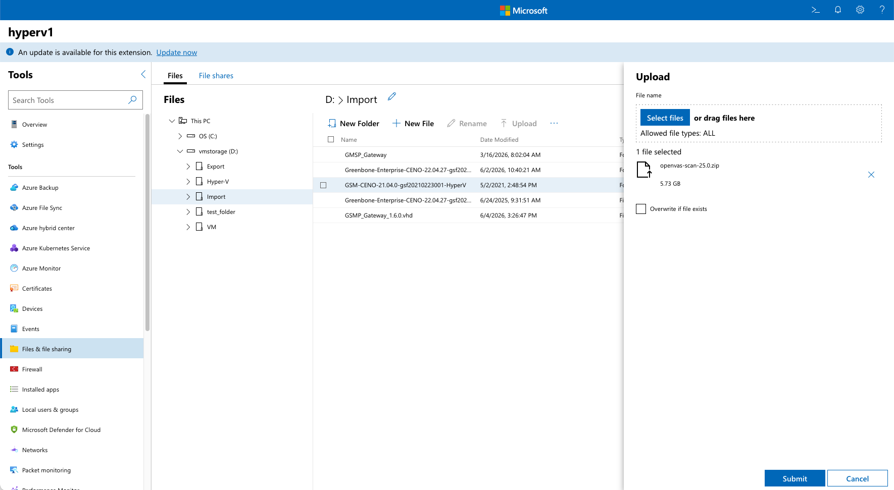
Fig. 4.2 Selecting the ZIP file
Click Submit.
→ The file is displayed in the table.
Select the ZIP file in the list and click Extract.
Click OK.
→ The extracted folder is displayed in the table.
Select Virtual machines in the menu.
Click Add and select Import from the drop-down list.
Select the folder that contains the virtual machine files.
Select the virtual machine from the VM drop-down list.
Click Import.
→ The virtual machine is being imported. This can be a lengthy process.
When the import is finished, the virtual machine is displayed in the table.
Select the virtual machine in the list, click Power and select Start from the drop-down list.
→ The appliance will boot and after a short time – depending on the exact model – the login prompt is shown.
Log in using the default login information:
User:
adminPassword:
admin
Note
During the first setup, this password should be changed (see Chapter 6.2.1.1).
4.3.2.1.2 Hyper-V Manager
To deploy an appliance, import it into the hypervisor as follows:
Note
File and folder names used in the example differ based on the hypervisor configuration and the subscription key.
Unzip the ZIP file of the appliance.
Note
The extracted folder contains a sub-folder with the same name. This sub-folder is required for the import.
Open Hyper-V Manager.
Click Import Virtual Machine… on the right side.
→ The import wizard is opened.
Click Next >.
Click Browse, select the sub-folder of the extracted folder and click Next >.
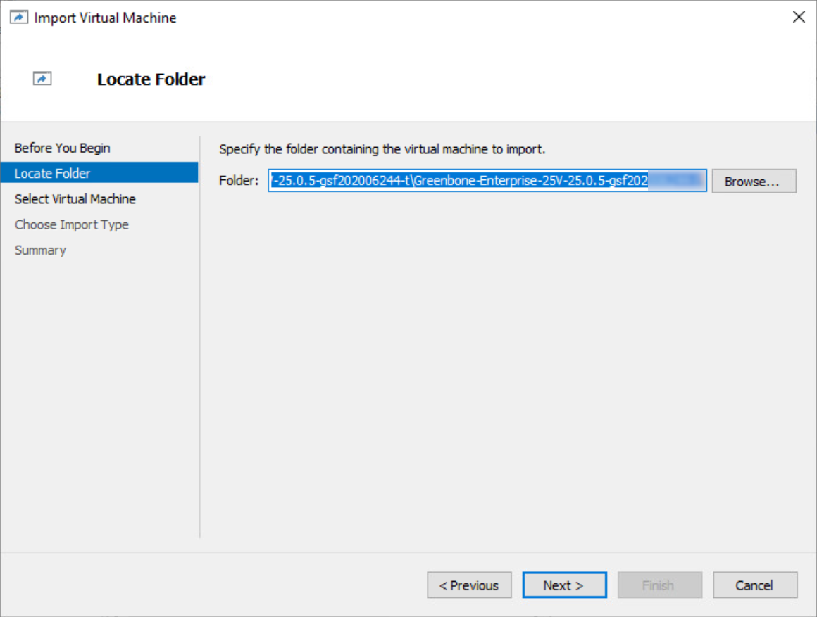
Fig. 4.3 Selecting the sub-folder
Select the virtual machine and click Next >.
Select the radio button Register the virtual machine in-place and click Next >.
Click Finish.
→ The virtual machine is being imported. This can be a lengthy process.
When the import is finished, the virtual machine is displayed in the Virtual Machines section.
Right-click on the virtual machine and select Start.
→ The appliance will boot.
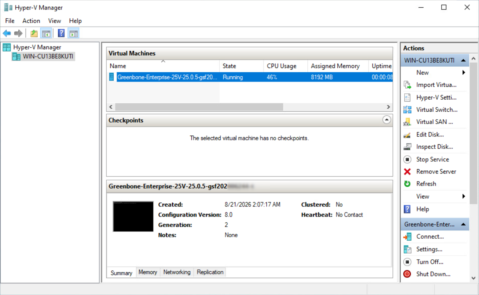
Fig. 4.4 Selecting the appliance
Right-click on the appliance and select Connect….
→ The login prompt is shown.
Log in using the default login information:
User:
adminPassword:
admin
Note
During the first setup, this password should be changed (see Chapter 6.2.1.1).
4.3.2.2 VMware vSphere/ESXi
The virtual appliance is provided by Greenbone in the Open Virtualization Appliance (OVA) format.
Each appliance is activated using a unique subscription key.
Note
Cloning the appliance and using several instances in parallel is not permitted and can result in inconsistencies and unwanted side effects.
To deploy an appliance, import it into the hypervisor as follows:
Note
The example features VMware ESXi, but is also applicable for VMware vCenter.
File and folder names used in the example differ based on the hypervisor configuration and the subscription key.
Open the web interface of the VMware ESXi instance and log in.
Click Virtual Machines in the Navigator column on the left.
Click
 Create / Register VM.
Select Deploy a virtual machine from an OVF or OVA file and click Next (see Fig. 4.5).
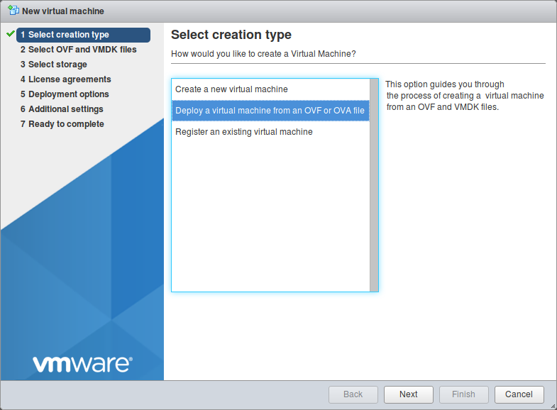
Fig. 4.5 Selecting the creation type
Enter a name for the virtual machine in the input box.
Click Click to select files or drag/drop, select the OVA file of the appliance and click Next.
Select the storage location in which to store the virtual machine files and click Next.
Adjust the deployment options as required and click Next.
Note
The default deployment settings may be used.
Check the configuration of the virtual machine (see Fig. 4.6).
Tip
Settings can be changed by clicking Back and adjusting them in the respective dialog.
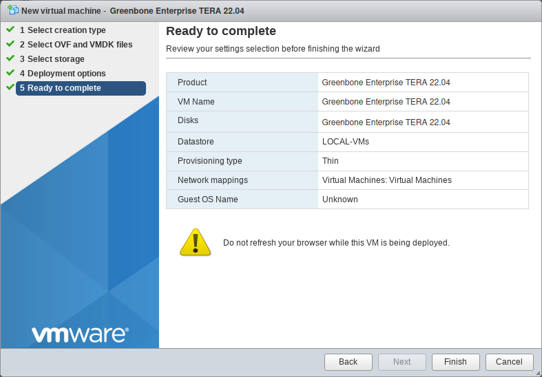
Fig. 4.6 Checking the configuration of the virtual machine
Click Finish.
→ The virtual machine is being imported. This can be a lengthy process.
Important
Do not refresh the browser while the virtual machine is being imported.
When the import is finished, click Virtual Machines in the Navigator column on the left.
Select the virtual machine in the list and click
 Power on (see Fig. 4.7).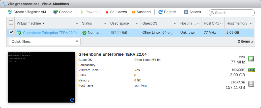
Fig. 4.7 Imported virtual machine
→ The appliance will boot and after a short time – depending on the exact model – the login prompt is shown.
Log in using the default login information:
User:
adminPassword:
admin
Note
During the first setup, this password should be changed (see Chapter 6.2.1.1).
4.3.2.3 Oracle VirtualBox
The virtual appliance is provided by Greenbone in the Open Virtualization Appliance (OVA) format.
Each appliance is activated using a unique subscription key.
Note
Cloning the appliance and using several instances in parallel is not permitted and can result in inconsistencies and unwanted side effects.
To deploy an appliance, import it into the hypervisor as follows:
Note
File and folder names used in the example differ based on the hypervisor configuration and the subscription key.
Install Oracle VirtualBox for the current operating system.
Note
VirtualBox is often included with Linux distributions.
If this is not the case, or if Microsoft Windows is used, VirtualBox is available from the Oracle VirtualBox download page.
Start VirtualBox.
Select File > Import Appliance… in the menu.
Click
 and select the OVA file of the appliance (see Fig. 4.8).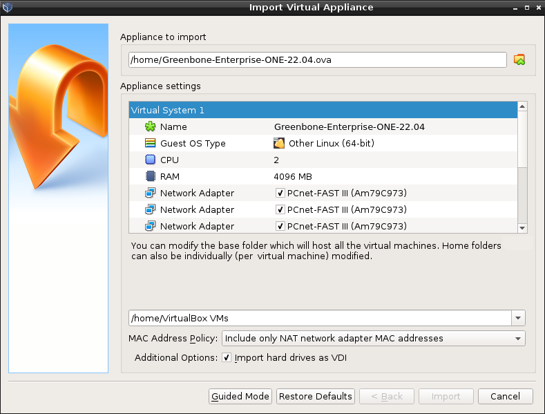
Fig. 4.8 Importing the OVA file of the appliance
Check the configuration of the virtual machine in the window Appliance settings (see Fig. 4.8).
Values can be changed by double-clicking into the input box of the respective value.
Click Import.
→ The virtual machine is being imported. This can be a lengthy process.
When the import is finished, the virtual machine is displayed in the left column in VirtualBox.
Select the virtual machine in the list and click Start.
→ The appliance will boot and after a short time – depending on the exact model – the login prompt is shown.
Log in using the default login information:
User:
adminPassword:
admin
Note
During the first setup, this password should be changed (see Chapter 6.2.1.1).
4.3.2.4 Proxmox Virtual Environment
The virtual appliance is provided by Greenbone as a compressed Proxmox backup using the Zstandard (ZST) format.
Each appliance is activated using a unique subscription key.
Note
Cloning the appliance and using several instances in parallel is not permitted and can result in inconsistencies and unwanted side effects.
To deploy an appliance, import it into the hypervisor as follows:
Note
File and folder names used in the example differ based on the hypervisor configuration and the subscription key.
Copy the ZST file to the
/var/lib/vz/dump/directory of the Proxmox Virtual Environment instance.Open the web interface of the Proxmox Virtual Environment instance and log in.
Click Datacenter in the column on the left and select the respective node and storage.
Note
Backups must be enabled for the storage device to be used.
Click Backups in the column in the middle (see Fig. 4.9).
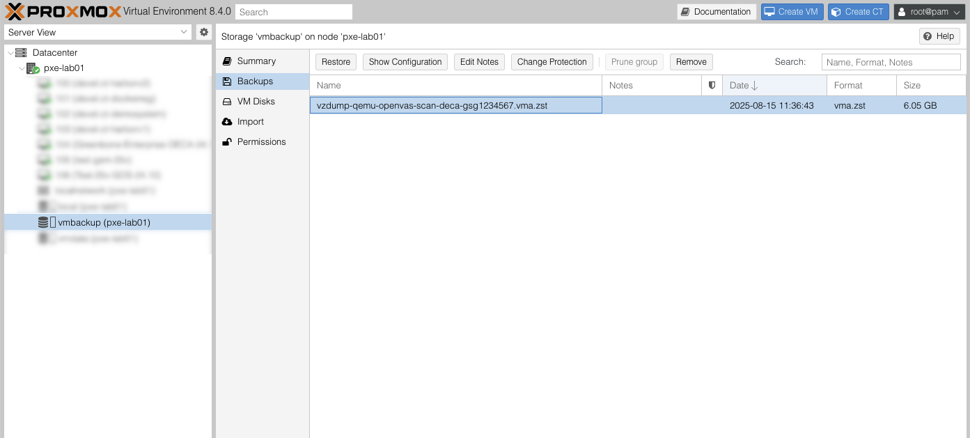
Fig. 4.9 Selecting the ZST file
Select the ZST file copied in step 1 and click Restore.
Check the configuration of the virtual machine in the window Restore: VM (see Fig. 4.10).
Values can be changed by double-clicking into the input box of the respective value.
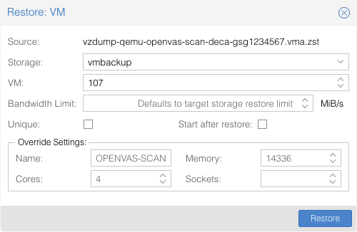
Fig. 4.10 Checking the configuration of the virtual machine
Click Restore.
→ The virtual machine is being imported. This can be a lengthy process.
When the import is finished, the virtual machine is displayed in the column on the left.
Select the virtual machine and click Start.
→ The appliance will boot and after a short time – depending on the exact model – the login prompt is shown.
Log in using the default login information:
User:
adminPassword:
admin
Note
During the first setup, this password should be changed (see Chapter 6.2.1.1).
4.3.2.5 Nutanix AHV
The virtual appliance is provided by Greenbone in the QEMU Copy-On-Write (QCOW) format.
Each appliance is activated using a unique subscription key.
Note
Cloning the appliance and using several instances in parallel is not permitted and can result in inconsistencies and unwanted side effects.
To deploy an appliance, import it into the hypervisor as follows:
Note
File and folder names used in the example differ based on the hypervisor configuration and the subscription key.
Open the web interface of the Nutanix AHV instance and log in.
Click
 in the upper right corner.
Select Image Configuration in the menu.
Click Upload Image.
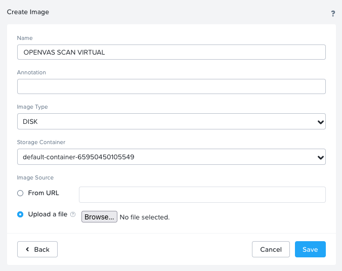
Fig. 4.11 Uploading the image
Enter a name for the image.
Select DISK in the drop-down list Image Type.
Select the radio button Upload a file, click Browse… and select the QCOW file of the appliance.
Click Save.
Click on the drop-down menu in the upper left corner and select VM.
Click Create VM.
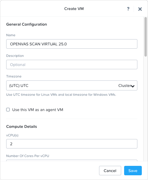
Fig. 4.12 Creating the virtual machine
Enter a name for the virtual machine.
Enter the number of virtual CPUs and the number of cores per virtual CPU.
Enter the amount of memory.
Select the radio button UEFI for the boot configuration.
Click Add New Disk.
→ The dialog for adding a disk is opened.
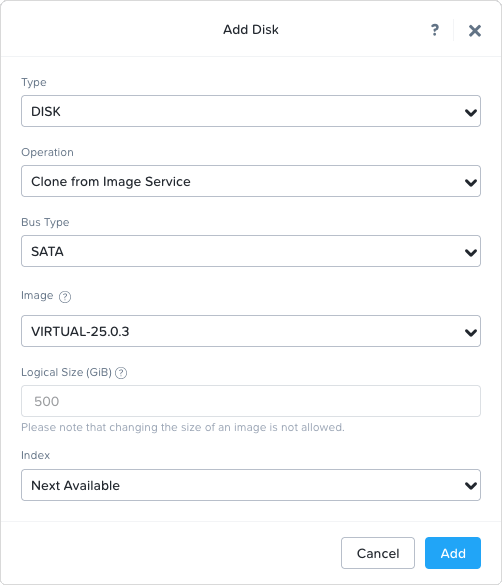
Fig. 4.13 Adding the disk
Select Clone from Image Service in the Operation drop-down list.
Select SATA in the Bus Type drop-down list.
Select the image created in steps 2–8 in the Image drop-down list.
Click Add.
→ The dialog is closed.
Click Add New NIC in the section Network Adapters (NIC).
→ The dialog for adding a network interface is opened.
Note
When using the community edition of Nutanix AHV, the combination of network interfaces and UEFI can cause issues when starting the virtual machine.
A workaround for this is to add e1000 network interfaces to the virtual machine. This can be done via SSH on the Nutanix host by running the following command:
acli vm.nic_create NAMEOFVIRTUALMACHINE model=e1000 network=NAMEOFNETWORK
Add at least one network interface.
Note
A maximum of 8 interfaces can be configured.
Click Add.
→ The dialog is closed.
Click Save.
→ The virtual machine is being imported. This can be a lengthy process.
When the import is finished, select the Table tab in the upper left corner.
→ The virtual machine is displayed in the table.
Select the virtual machine in the list and click Power on.
→ The appliance will boot and after a short time – depending on the exact model – the login prompt is shown.
Log in using the default login information:
User:
adminPassword:
admin
Note
During the first setup, this password should be changed (see Chapter 6.2.1.1).
4.4 Performing a General System Setup
All appliances use the same procedure for basic configuration and the readiness check.
When the appliance is delivered by Greenbone or after a factory reset, the GOS administration menu shows the first setup wizard after logging in to assist with the basic GOS configuration (see Fig. 4.14).
By selecting Yes and pressing Enter the first setup wizard is opened.
By selecting No and pressing Enter, the setup wizard is closed. Incomplete steps are displayed again when logging in the next time.
By selecting Cancel and pressing Enter, the setup wizard is closed as well. However, incomplete steps are not displayed again.
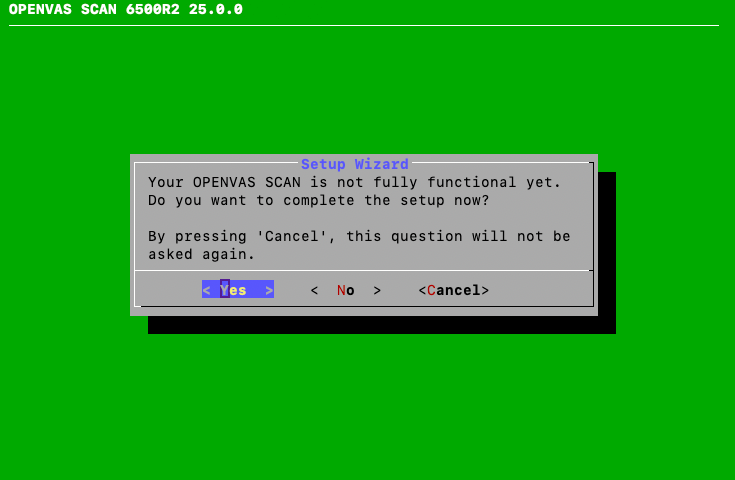
Fig. 4.14 Using the first setup wizard
Note
The first setup wizard is dynamic and shows only those steps necessary to operate the used appliance model. In the following, all possible steps are mentioned but they may not appear in every case.
After a factory reset, all steps must be carried out (see Chapter 20.10).
Every step can be skipped by selecting Skip or No and pressing Enter. Skipped steps are displayed when logging in again.
When the appliance is delivered by Greenbone or after a factory reset, the GOS administration menu uses the US keyboard layout. The keyboard layout can later be changed in the GOS administration menu as described in Chapter 6.2.19.
4.4.1 Configuring the Network
The network must be set up for the appliance to be fully functional. If no IP address is configured, the first setup wizard asks whether the network settings should be configured (see Fig. 4.15).
Note
When using DHCP, the appliance does not transmit the MAC address but a DHCP Unique ID (DUID). While this should not pose a problem with modern DHCP servers, some older DHCP servers (for example Windows Server 2012) may not be able to handle it.
One possible solution is to specify the DUID instead of the MAC address on the DHCP server. Alternatively, a static IP address can be used on the appliance.
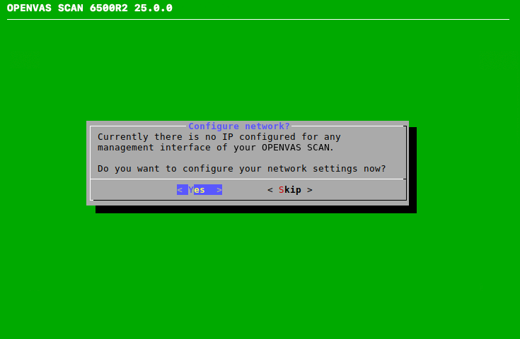
Fig. 4.15 Configuring the network settings
Select Yes and press Enter.
Select Interfaces and press Enter.
Select the desired interface and press Enter.
→ The interface can be configured.
To use DHCP, select DHCP (for IPv4 or IPv6) and press Enter (see Fig. 4.16).
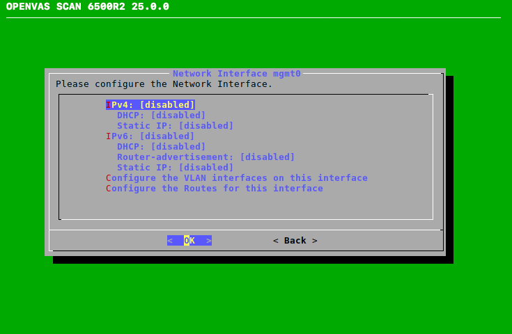
Fig. 4.16 Configuring the network interface
Select Save and press Enter.
Select Back and press Enter.
Select Back and press Enter.
Select Ready and press Enter.
or
To use a static IP address, select Static IP (for IPv4 or IPv6) and press Enter.
Enter the IP address including the prefix length in the input box (see Fig. 4.17).
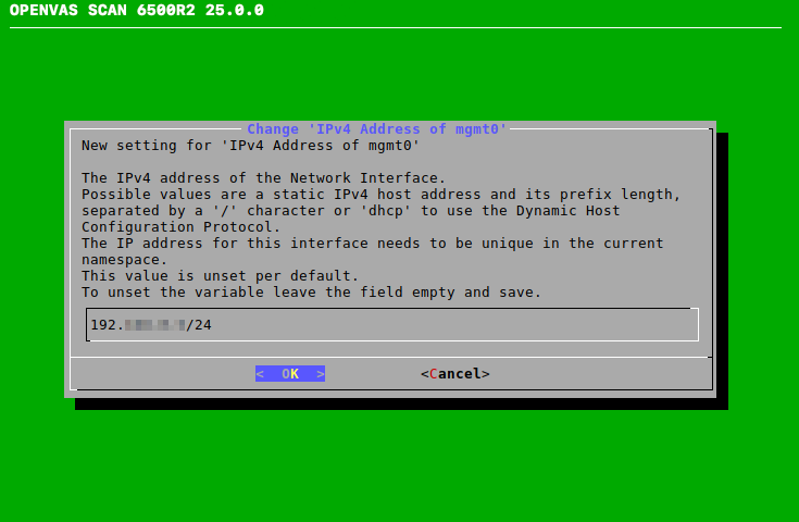
Fig. 4.17 Entering a static IP address
Press Enter.
→ A message indicates that the changes must be saved.
Press Enter to close the message.
Select Save and press Enter.
Select Back and press Enter.
Select Back and press Enter.
Select Ready and press Enter.
4.4.2 Importing or Generating an HTTPS Certificate
An HTTPS certificate is recommended for using the web interface securely. The certificate can be imported or generated as follows:
Select Import and press Enter (see Fig. 4.18).
→ A message indicates that a PKCS#12 file can be imported.
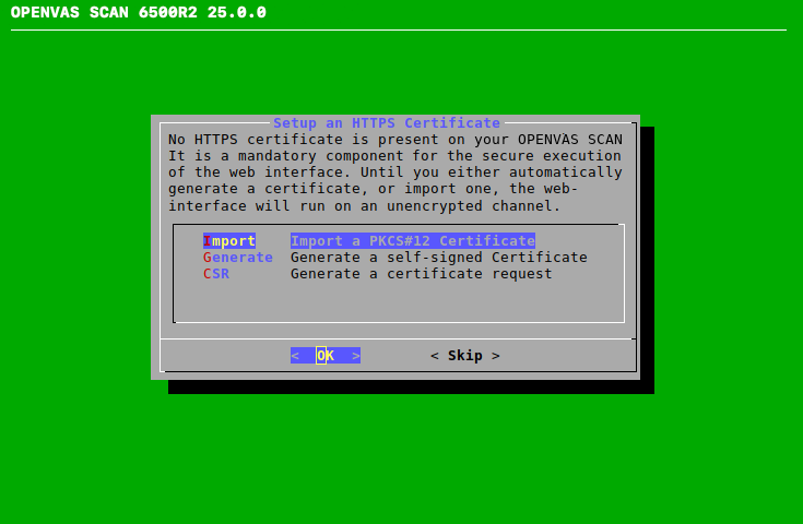
Fig. 4.18 Importing or generating an HTTPS certificate
Select Continue and press Enter.
Open the web browser and enter the displayed URL.
Click Browse…, select the PKCS#12 file and click Upload.
→ When the certificate is retrieved by the appliance, the GOS administration menu displays the fingerprint of the certificate for verification.
Check the fingerprint and confirm the certificate by pressing Enter.
or
Select Generate and press Enter.
→ A message indicates that parameters must be entered to generate the certificate.
Select Continue and press Enter.
Provide the settings for the certificate (see Fig. 4.19).
Note
It is valid to generate a certificate without a common name. However, a certificate should not be created without at least one Subject Alternative Name (SAN).
If a common name is used, it should be the same as one of the SANs.
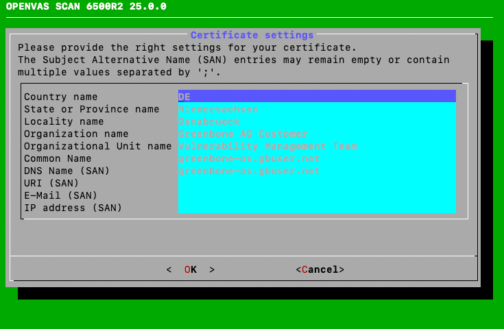
Fig. 4.19 Entering information for the certificate
Select OK and press Enter.
→ A message indicates that the certificate has been created and can be downloaded (see Fig. 4.20).
Note
The certificate cannot be downloaded from the first setup wizard. It can be downloaded later from the GOS administration menu as described in Chapter 6.2.4.8.2.
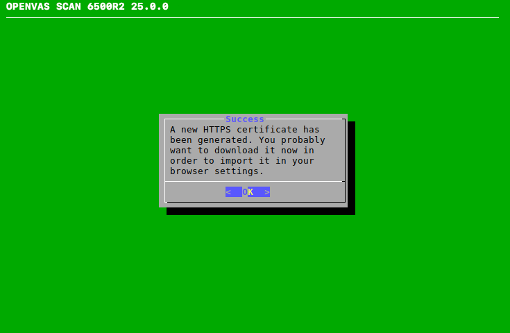
Fig. 4.20 Completing the HTTPS certificate
or
Select CSR and press Enter.
→ A message indicates that a key pair and certificate request have been created.
Select Continue and press Enter.
Provide the settings for the certificate.
Note
It is valid to generate a certificate without a common name. However, a certificate should not be created without at least one Subject Alternative Name (SAN).
If a common name is used, it should be the same as one of the SANs.
Select OK and press Enter.
Open the web browser and enter the displayed URL.
Download the PEM file.
→ The GOS administration menu displays a message containing information for verifying that the CSR has not been tampered with.
Check the information and press Enter to confirm.
Note
When the certificate is signed, it must be uploaded to the appliance. The signed certificate cannot be uploaded from the first setup wizard. It can be uploaded later from the GOS administration menu as described in Chapter 6.2.4.8.3.
4.4.3 Creating a Web Administrator
If no web administrator exists, the first setup wizard asks whether such an account should be created (see Fig. 4.21).
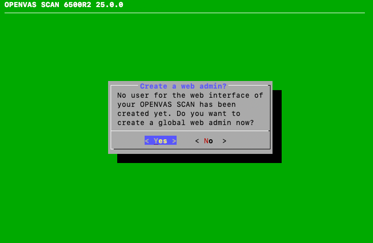
Fig. 4.21 Creating a web administrator
Note
A web administrator is required to use the web interface of the appliance.
The first web administrator (web user) that is created is automatically the Feed Import Owner (see Chapter 6.2.1.10).
Select Yes and press Enter.
Enter the user name for the web administrator.
Note
Only the following characters are allowed for the user name:
All alphanumeric characters
- (dash)
_ (underscore)
. (full stop)
Enter the password for the web administrator twice.
Note
The password can contain any type of character and can be at most 64 characters long.
When using special characters, note that these must be available on all used keyboards and correctly supported by all client software and operating systems. Copying and pasting special characters for passwords can lead to invalid passwords depending on these external factors.
Select OK and press Enter.
→ A message indicates that the web administrator has been created.
Press Enter to close the message.
4.4.4 Entering or Uploading an OPENVAS ENTERPRISE FEED Subscription Key
If no valid OPENVAS ENTERPRISE FEED subscription key is stored on the appliance, the appliance only uses the public OPENVAS COMMUNITY FEED instead. This does not apply to OPENVAS BASIC, which requires an OPENVAS ENTERPRISE FEED subscription key and cannot be used with the OPENVAS COMMUNITY FEED.
Note
It is not necessary to add an OPENVAS ENTERPRISE FEED subscription key on a newly delivered appliance since a subscription key is already pre-installed.
A subscription key can be entered or uploaded as follows:
Select Editor and press Enter (see Fig. 4.22).
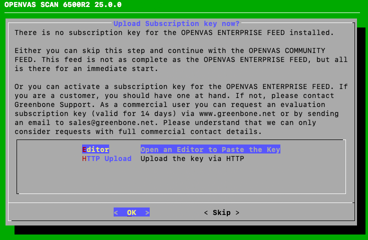
Fig. 4.22 Entering or uploading a subscription key
→ The editor is opened.
Enter the content of the subscription key.
Note
It is important to enter the content of the subscription key and not its name (for example
gsf2022122017).The content of the subscription key can be displayed with any text editor or under Linux using the program
less. If the content is opened with a text editor, care must be taken not to modify the content.Press Ctrl + S to save the changes.
Press Ctrl + X to close the editor.
or
Select HTTP Upload and press Enter.
Open the web browser and enter the displayed URL.
Click Browse…, select the subscription key and click Upload.
4.4.5 Downloading the Feed
If no feed is present on the appliance, the feed can be downloaded as follows:
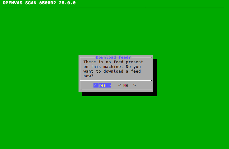
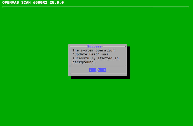
4.4.6 Finishing the First Setup Wizard
Note
After the last step, a self check is performed.
When the self check is finished, press Enter.
→ The results of the self check are displayed (see Fig. 4.25).
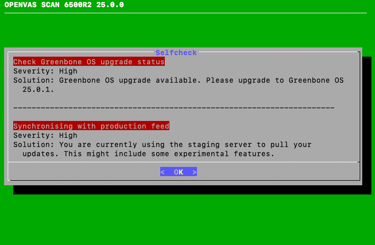
Fig. 4.25 Result of the self check
Press Enter.
→ The GOS administration menu can be used as described in Chapter 6.
If there are any unfinished or skipped steps, the first setup wizard is shown when logging in again.
4.5 Accessing the Web Interface
Note
This step does not apply for OPENVAS SCAN 35 and OPENVAS SCAN 25V.
The main interface of the appliance is the web interface, also called Greenbone Security Assistant (GSA). The web interface can be accessed as described in Chapter 7.1.