5 Scanning a System
5.1 Using the Task Wizard for a Scan
The task wizard can configure and start a scan with minimal user input.
Select Scan Management in the menu panel.
Click + Prepare New Scan Task with Wizard.
→ An information message is displayed.
Click Let’s go!
Note
If the message should not be displayed again, activate the checkbox Do not show again before clicking Let’s go!
Enter the name for the task in the input box Task name (see Fig. 5.1).
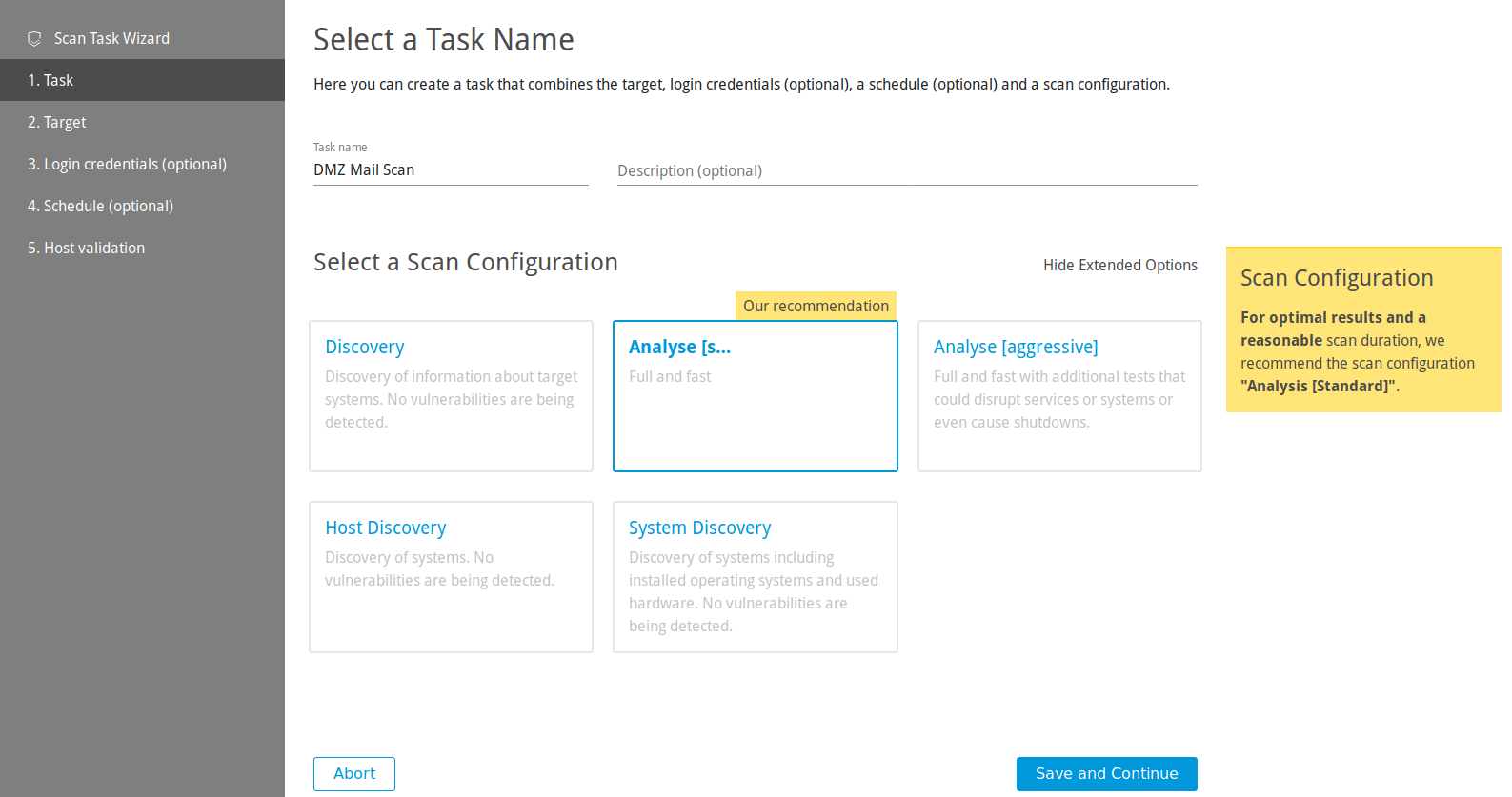
Fig. 5.1 Using the wizard
Optional: enter a description for the task in the input box Description (optional).
Select the scan configuration.
Click Save and Continue.
Note
When the wizard is used, only external target can be scanned.
Select an already available target from the list.
or
Click + Create New Target to create a new target.
Tip
For the information to enter in the input boxes see Chapter 5.2.1.
Click Save and Continue.
Optional: select already available credentials for Microsoft Windows login (SMB), SSH, or VMware ESXi from the list.
or
Optional: click + Create New Login Credentials to create new credentials.
Tip
For the information to enter in the input boxes see Chapter 5.3.2.1.
Click Save and Continue.
Optional: select an already available schedule from the list.
or
Optional: click + Create New Schedule to create a new schedule.
Tip
For the information to enter in the input boxes see Chapter 5.4.1.
Click Save and Continue.
Note
If an external target was chosen and the host(s) have not been validated yet, Request Host Validation is displayed for the host(s) (see Fig. 5.2).

Fig. 5.2 Host(s) not validated yet
To carry out the host validation, click Request Host Validation.
→ The contacts for the configured host(s) are collected from RIPE NCC. For more information see Chapter 5.2.2.
When this process is finished, an overlay displays the found contact (see Fig. 5.3).
Note
If no contact was found, the hosts have to be checked manually by the vMSP’s security team.
Activate the checkbox for I Am The Owner, select the contact person from the list, or activate the checkbox for a manual check by the vMSP’s security team.
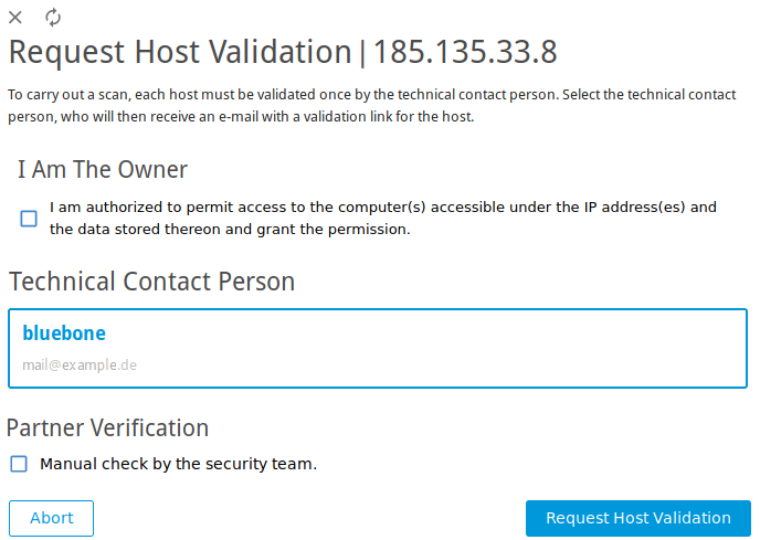
Fig. 5.3 Selecting contact for the host validation
Click Request Host Validation.
→ An e-mail is sent to the contact person or the security team. The status of the host validation is displayed on the page Targets.
Click Prepare Scan.
→ The page Scan Management is opened. The new task has the status Available.
In the row of the created task click
 .
.It can take a while for the scan to complete. The page is refreshing automatically if new data is available.
For the status of a task see Chapter 5.7.
Tip
The report of a task can be displayed as soon as the task has been started by clicking ![]() for the respective task on the page Scan Management.
for the respective task on the page Scan Management.
For reading, managing and downloading reports see Chapter 6.
As soon as the status changes to Done the complete report is available. At any time the intermediate results can be reviewed (see Chapter 6.1).
5.2 Configuring a Simple Scan Manually
The Greenbone Cloud Service can use two different approaches to scan a target:
Simple scan
Authenticated scan using local security checks (see Chapter 5.3)
The following steps have to be executed to configure a simple scan:
Creating a target (see Chapter 5.2.1)
Validating the host(s) (see Chapter 5.2.2) or creating a gateway (see Chapter 5.2.3)
Creating a task (see Chapter 5.2.4)
Starting the task (see Chapter 5.2.5)
5.2.1 Creating a Target
The first step is to define an external or an internal scan target.
5.2.1.1 Creating an External Target
Select Targets (category Scan Configuration) in the menu panel.
Click External Targets.
Create a new target by clicking + Create New External Target.
Select the target mode by clicking IP Address or Hostname. It defines the form in which the target is specified.
Note
The target mode cannot be changed after initially creating the target.
A mixed target mode is not possible.
Define the target (see Fig. 5.4).
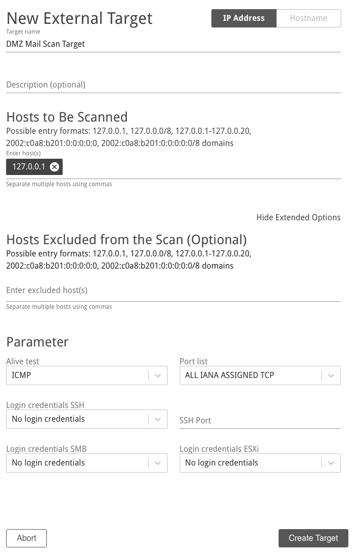
Fig. 5.4 Creating a new target
Click Create Target.
Note
A host validation is necessary for scanning an external target (see Chapter 5.2.2).
The following information can be entered:
- Target name
The name can be chosen freely. A descriptive name should be chosen if possible.
- Description (optional)
The optional comment allows specifying background information. It simplifies understanding the configured targets later.
- Hosts to Be Scanned (for target mode IP Address)
Manual entry of the hosts that should be scanned, separated by commas.
Note
The IP address or the host name is required. In both cases it is necessary that the Greenbone Cloud Service can connect to the system. If using the host name, the Greenbone Cloud Service must also be able to resolve the name.
For entering the following options are available:
Single IPv4 address, for example 192.168.15.5
Domain name, for example example.com
IPv4 address range, for example 192.168.15.5-192.168.15.27
IPv4 address range in CIDR notation, for example 192.168.15.0/24
Single IPv6 address, for example fe80::222:64ff:fe76:4cea
IPv6 address range in CIDR notation, for example fe80::222:64ff:fe76:4cea/120
Multiple options can be mixed.
- Hosts Excluded from the Scan (Optional) (for target mode IP Address)
Manual entry of the hosts that should be excluded from the list mentioned above, separated by commas.
The same specifications as for Hosts to Be Scanned apply.
- Hostnames to be Scanned (for target mode Hostname)
Manual entry of the hosts that should be scanned, separated by commas.
Note
The host name is required. It is necessary that the Greenbone Cloud Service can connect to the system. The Greenbone Cloud Service must also be able to resolve the host name.
- Alive test
This options specifies the method to check if a target is reachable. Options are:
TCP ack service
ICMP
Consider alive
TCP syn service
- Port list
Port list used for the scan (see Chapter 5.9).
- Login credentials SSH
Selection of a user that can log into the target system of a scan if it is a Linux or Unix system. This allows for an authenticated scan using local security checks (see Chapter 5.3).
- Login credentials SMB
Selection of a user that can log into the target system of a scan if it is a Microsoft Windows system. This allows for an authenticated scan using local security checks (see Chapter 5.3).
- Login credentials ESXi
Selection of a user that can log into the target system of a scan if it is a VMware ESXi system. This allows for an authenticated scan using local security checks (see Chapter 5.3).
5.2.1.2 Creating an Internal Target
Select Targets (category Scan Configuration) in the menu panel.
Click Internal Targets.
Create a new target by clicking + Create New Internal Target.
Define the target.
Click Create Target.
Note
A gateway has to be used for scanning an internal target (see Chapter 5.2.3).
The following information can be entered:
- Target name
The name can be chosen freely. A descriptive name should be chosen if possible.
- Description (optional)
The optional comment allows specifying background information. It simplifies understanding the configured targets later.
- Hosts to Be Scanned
Manual entry of the hosts that should be scanned, separated by commas.
Note
The IP address or the host name is required. In both cases it is necessary that the Greenbone Cloud Service can connect to the system. If using the host name, the Greenbone Cloud Service must also be able to resolve the name.
For entering the following options are available:
Single IPv4 address, for example 192.168.15.5
Domain name, for example example.com
IPv4 address range, for example 192.168.15.5-192.168.15.27
IPv4 address range in CIDR notation, for example 192.168.15.0/24
Multiple options can be mixed.
- Hosts Excluded from the Scan (Optional)
Manual entry of the hosts that should be excluded from the list mentioned above, separated by commas.
The same specifications as for Hosts to Be Scanned apply.
- Alive test
This options specifies the method to check if a target is reachable. Options are:
TCP ack service
ICMP
Consider alive
TCP syn service
- Port list
Port list used for the scan (see Chapter 5.9).
- Login credentials SSH
Selection of a user that can log into the target system of a scan if it is a Linux or Unix system. This allows for an authenticated scan using local security checks (see Chapter 5.3).
- Login credentials SMB
Selection of a user that can log into the target system of a scan if it is a Microsoft Windows system. This allows for an authenticated scan using local security checks (see Chapter 5.3).
- Login credentials ESXi
Selection of a user that can log into the target system of a scan if it is a VMware ESXi system. This allows for an authenticated scan using local security checks (see Chapter 5.3).
5.2.2 For External Targets: Validating the Hosts
If an external target is created, the defined hosts must be validated. Scanning targets without host validation is not possible.
A host can be validated by the following persons:
By the users themselves if they are the owner of the host(s)
By the person responsible for the host(s)
By the security team of the vMSP
5.2.2.1 Validation by the User as the Owner
The host can be validated by the user.
Note
The user must confirm that they are authorized to permit access to the computer(s) accessible under the IP address(es) and the data stored on them. By accepting this, the user assumes all responsibility for vulnerability scans performed against the corresponding computer(s) as well as for all effects and consequences that may arise from the scans. Any third-party complaints or requests will be forwarded directly to the user by Greenbone, and Greenbone will not further process nor provide any assistance in case of complaints or requests.
Select Targets (category Scan Configuration) in the menu panel.
Click External Targets.
→ If the validation has not been completed yet,
 is displayed in the column Verified.
In the row of the target click
 .
.Click Request Host Validation (see Fig. 5.5).
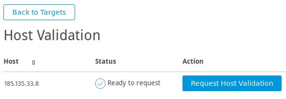
Fig. 5.5 Requesting the host validation
Activate the checkbox I Am The Owner (see Fig. 5.6).
Fig. 5.6 Selecting contact for the host validation
Click Validate Host.
→ When the hosts are validated,
 is displayed in the column Verified on the page Targets.
5.2.2.2 Validation by the Contact Person or by the vMSP’s Security Team
The responsible contact person – if available – is obtained from RIPE NCC. RIPE NCC is the Regional Internet Registry (RIR) for Europe, the Middle East and parts of Central Asia and allocates and registers IP address ranges.
If no contact is found, the hosts can be checked manually by the vMSP’s security team.
Select Targets (category Scan Configuration) in the menu panel.
Click External Targets.
→ If the validation has not been completed yet,
is displayed in the column Verified.In the row of the target click
.Click Request Host Validation (see Fig. 5.5).
→ The contacts for the configured host are collected from RIPE NCC.
When this process is finished, an overlay displays the found contact (see Fig. 5.6).
Select the contact person from the list.
or
If no contact person was found, activate the checkbox Manual check by the security team.
Click Request Host Validation.
→ An e-mail is sent to the contact person or the security team.
Note
By clicking Reset Contact Selection the selected contact is rejected.
If the hosts are validated,
is displayed in the column Verified on the page Targets.If the host validation is rejected,
 is displayed in the column Verified on the page Targets.
5.2.3 For Internal Targets: Creating a Gateway
If an internal target in the customer’s network should be scanned, a gateway must be used.
Resources
The gateway requires at least the following resources:
1 virtual CPU
512 MB RAM
8 GB hard disk
Supported Hypervisors
The following hypervisors are officially supported for running the gateway:
Microsoft Hyper-V, version 5.0 or higher
VMware vSphere Hypervisor (ESXi), version 6.0 or higher
Note
Depending on the used virtual environment, the settings described under Configurations for Environment have to be configured (see Fig. 5.7).
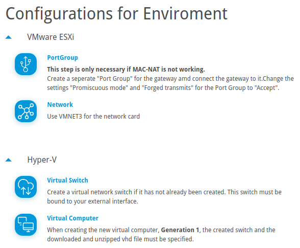
Fig. 5.7 Advanced virtual environment settings
5.2.3.1 Setting up a Gateway
A gateway can be set up as follows:
Select Gateways (category Scan Configuration) in the menu panel.
Select the desired virtual environment in the drop-down list Download and click
 .
.Import the gateway to the virtual environment.
Start the gateway in the virtual environment.
After the boot process is completed, the login prompt is shown. The default login information is:
Login name:
adminPassword:
admin
→ The gateway administration menu is opened.
Select Gateway configuration and press Enter.
Select Set web password and press Enter.
Enter the password twice and press Tab (see Fig. 5.8).
Note
The password has to fulfill the following criteria:
At least 8 characters
Contains upper and lower cases
Contains at least one special character
Contains at least one number

Fig. 5.8 Setting the password for the gateway web interface
Press Enter.
Select Save changes and press Enter.
→ A message is displayed, informing that the gateway has been configured successfully.
Press Enter to close the message.
Select Network configuration and press Enter.
Note
For all configuration options see Chapter 5.6.2.
Note the displayed IP address of the gateway (see Fig. 5.9). It is needed for accessing the gateway web interface.
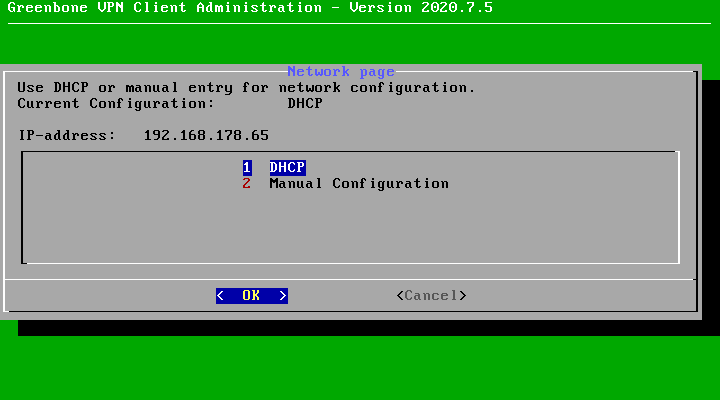
Fig. 5.9 IP address of the gateway
On the platform, click + Create New Gateway.
Enter a textual description of the gateway’s location in the input box Location (see Fig. 5.10).
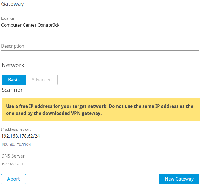
Fig. 5.10 Creating a new gateway
Optional: enter a description for the gateway in the input box Description.
Enter a free IP address from the network that should be scanned including the prefix length in the input box IP address/network.
Note
The entered IP address must differ from the IP address of the gateway.
Enter the IP address of a DNS server located in the target network in the input box DNS Server.
Note
By default, MAC-NAT is enabled.
If MAC-NAT does not work, click Advanced and deactivate the checkbox Use MAC-NAT.
Note
If VMware ESXi is used, configure the settings displayed on the page Gateways under Configurations for Environment.
Note
If a network is to be scanned in which the scanner is not located, network routing can be used as described in steps 20-23.
Click + Create New Route.
Define the route by entering the network and the gateway located in the network in the respective input boxes.
Enter the metric information in the input box Metric.
The metric is important if there are multiple routes for the same target network. In this case, the best route is the one with the smallest metric value.
Click Save.
→ The route is displayed in the table.
Click New Gateway.
→ The gateway is created and displayed on the page Gateways.
5.2.3.2 Registering the Gateway
The gateway must be registered either via gateway web interface or via gateway administration menu (CLI).
Registration via gateway web interface
The registration via gateway web interface is carried out as follows:
In the row of the gateway click
 .
.Select WEB.
Click Copy to Clipboard to copy the API key.
Open the web browser and enter the following URL:
https://<ip>. Replace<ip>with the IP address of the gateway (see step 13 in Chapter 5.2.3.1).Log in using the user name
adminand the password defined in steps 6–9 in Chapter 5.2.3.1.Select Settings in the menu panel.
Paste the API key in the input box API-Key.
Click Save.
→ On the page Gateways on the platform, the column Status displays CONNECTED (see Fig. 5.11).
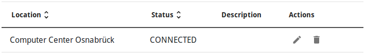
Fig. 5.11 Connecting the gateway
Registration via gateway administration menu (CLI)
The registration via gateway administration menu (CLI) is carried out as follows:
In the row of the gateway click
.Select CLI.
Note the URL and the token.
In the CLI, select Gateway configuration and press Enter.
Select Enter connection token (Optional) and press Enter.
Enter the URL and the token in the respective input boxes (see Fig. 5.12).
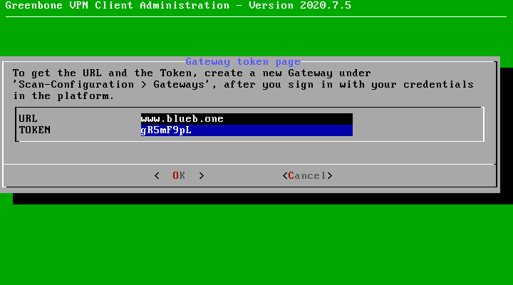
Fig. 5.12 Connecting the gateway
Press Tab and Enter.
→ On the page Gateways on the platform, the column Status displays CONNECTED (see Fig. 5.11).
5.2.4 Creating a Task
The next step is to create a task.
The Greenbone Cloud Service controls the execution of a scan using tasks. These tasks can be repeated regularly or run at specific times (see Chapter 5.4).
A task can be created as follows:
Select Scan Configuration in the menu panel.
Create a new task by clicking + Create New Task.
Define the task (see Fig. 5.13).
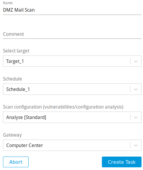
Fig. 5.13 Creating a new task
Click Create Task.
→ The task is created and displayed on the page Scan Configuration.
The following information can be entered:
- Name
The name can be chosen freely. A descriptive name should be chosen if possible.
- Comment
The optional comment allows for the entry of background information. It simplifies understanding the configured task later.
- Select target
Select a previously configured target from the drop-down list (see Chapter 5.2.1).
- Schedule
Select a previously configured schedule from the drop-down list (see Chapter 5.4). The task can be run once or repeatedly at a predetermined time, for example every Monday morning at 6:00 a.m.
Selecting a schedule is optional. If no schedule should be used, select Do not use a schedule.
- Scan configuration
The scan configuration specifies which vulnerability tests are performed during a scan.
The Greenbone Cloud Service comes with various predefined scan configurations (see Chapter 5.8).
The following option is only visible if an internal target is selected:
- Gateway
Select a previously configured gateway from the drop-down list (see Chapter 5.2.3).
5.2.5 Starting the Task
Select Scan Management in the menu panel. In the row of the desired task, click ![]() .
.
→ The scan is running.
It can take a while for the scan to complete. The page is refreshing automatically if new data is available.
For the status of a task see Chapter 5.7.
Tip
The report of a task can be displayed as soon as the task has been started by clicking ![]() for the respective task on the page Scan Management.
for the respective task on the page Scan Management.
For reading, managing and downloading reports see Chapter 6.
As soon as the status changes to Done the complete report is available. At any time the intermediate results can be reviewed (see Chapter 6.1).
5.3 Configuring an Authenticated Scan Using Local Security Checks
An authenticated scan can provide more vulnerability details on the scanned system. During an authenticated scan the target is both scanned from the outside using the network and from the inside using a valid user login.
During an authenticated scan, the Greenbone Cloud Service logs into the target system in order to run local security checks (LSC). The scan requires the prior setup of user credentials. These credentials are used to authenticate to different services on the target system. In some circumstances the results could be limited by the permissions of the users used.
The VTs in the corresponding VT families (local security checks) will only be executed if the Greenbone Cloud Service was able to log into the target system. The local security check VTs in the resulting scan are minimally invasive.
The Greenbone Cloud Service only determines the risk level but does not introduce any changes on the target system. However, the login by the Greenbone Cloud Service is probably logged in the protocols of the target system.
The Greenbone Cloud Service can use different credentials based on the nature of the target. The most important ones are:
- SMB
On Microsoft Windows systems, the Greenbone Cloud Service can check the patch level and locally installed software such as Adobe Acrobat Reader or the Java suite.
- SSH
This access is used to check the patch level on Unix and Linux systems.
- ESXi
This access is used for testing of VMware ESXi servers locally.
5.3.1 Advantages and Disadvantages of Authenticated Scans
The extent and success of the testing routines for authenticated scans depend heavily on the permissions of the used account.
On Linux systems, an unprivileged user is sufficient and can access most interesting information while especially on Microsoft Windows systems unprivileged users are very restricted and administrative users provide more results.
An unprivileged user does not have access to the Microsoft Windows registry and the Microsoft Windows system folder \windows which contains the information on updates and patch levels.
Local security checks are the most gentle method to scan for vulnerability details. While remote security checks try to be least invasive as well, they may have some impact.
Simply stated, an authenticated scan is similar to a Whitebox approach. The Greenbone Cloud Service has access to prior information and can access the target from within. Especially the registry, software versions and patch levels are accessible.
A remote scan is similar to a Blackbox approach. The Greenbone Cloud Service uses the same techniques and protocols as a potential attacker to access the target from the outside. The only information available was collected by the Greenbone Cloud Service itself. During the test, the Greenbone Cloud Service may provoke malfunctions to extract any available information on the used software. Example: the scanner may send a malformed request to a service to trigger a response containing further information on the deployed product.
During a remote scan using the scan configuration Analysis [Standard], all remote checks are safe. The used VTs may have some invasive components but none of the used VTs try to trigger a defect or malfunction in the target (see example below). All VTs with very invasive components or which may trigger a denial of service (DoS) are automatically excluded from the test.
Example for an Invasive VT
An example for an invasive but safe VT is the Heartbleed VT. It is executed even if VTs that may cause damage to the host system are disabled because the VT does not have any negative impact on the target.
The VT is still invasive because it tests the memory leakage of the target. If the target is vulnerable, actual memory of the target is leaked. The Greenbone Cloud Service does not evaluate the leaked information. The information is immediately discarded.
5.3.2 Using Credentials
Credentials for local security checks are required to allow VTs to log into target systems, for example for the purpose of locally checking the presence of all vendor security patches.
5.3.2.1 Creating Credentials
New credentials can be created as follows:
Select Login Credentials (category Scan Configuration) in the menu panel.
Create new credentials by clicking + Create New Login Credentials.
Define the credentials (see Fig. 5.14).
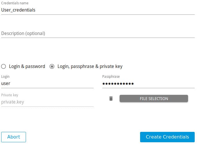
Fig. 5.14 Creating new credentials
Click Create Credentials.
The following details of the credentials can be defined:
Note
If the details contain German umlauts, the login does not work. The umlauts have to be replaced as follows:
“ß” → “ss”
“ä” → “a”
“ö” → “o”
“ü” → “u”
- Credentials name
Definition of the name. The name can be chosen freely.
- Description (optional)
An optional comment can contain additional information.
- Login & password/Login, passphrase & private key
Selection of the credential type.
Depending on the selected type, further options are shown:
- Login & password
- Login
Definition of the login name used by the Greenbone Cloud Service to authenticate on the scanned target system.
- Password
Definition of the password used by the Greenbone Cloud Service to authenticate on the scanned target system.
- Login, passphrase & private key
- Login
Definition of the login name used by the Greenbone Cloud Service to authenticate on the scanned target system.
- Passphrase
Definition of the passphrase of the private SSH key.
- Private key
Upload of the private SSH key by clicking FILE SELECTION.
An uploaded file can be deleted by clicking
 .
.
5.3.2.2 Managing Credentials
All existing credentials can be displayed by selecting Login Credentials in the menu panel.
For all credentials the following information is displayed:
- Name
Name of the credentials.
- Login Name
User name for the credentials.
- Comment
Optional additional information about the credentials.
For all credentials the following actions are available:
- Edit the credentials.
- Delete the credentials. Only credentials which are currently not used can be deleted.
5.3.3 Requirements on Target Systems with Microsoft Windows
5.3.3.1 General Notes on the Configuration
The remote registry service must be started in order to access the registry.
This is achieved by configuring the service to automatically start up. If an automatic start is not preferred, a manual startup can be configured. In that case, the service is started while the system is scanned by the Greenbone Cloud Service and afterwards it is disabled again. To ensure this behavior, the following information about LocalAccountTokenFilterPolicy must be considered.
It is necessary that for all scanned systems the file and printer sharing is activated. If using Microsoft Windows XP, take care to disable the setting Use Simple File Sharing.
For individual systems not attached to a domain the following registry key must be set:
HKLM\SOFTWARE\Microsoft\Windows\CurrentVersion\Policies\System\
DWORD: LocalAccountTokenFilterPolicy = 1
On systems with domain controller the user account in use must be a member of the group Domain Administrators to achieve the best possible results. Due to the permission concept it is not possible to discover all vulnerabilities using the Local Administrator or the administrators assigned by the domain. Alternatively follow the instructions in Chapter 5.3.3.2.
Should a Local Administrator be selected – which it explicitly not recommended – it is mandatory to set the following registry key as well:
HKLM\SOFTWARE\Microsoft\Windows\CurrentVersion\Policies\System\
DWORD: LocalAccountTokenFilterPolicy = 1
An exception rule for the Greenbone Cloud Service on the Microsoft Windows firewall must be created. Additionally, on XP systems the service File and Printer Sharing must be set to enabled.
5.3.3.2 Configuring a Domain Account for Authenticated Scans
For authenticated scans of Microsoft Windows target systems, it is highly recommended to use a domain account with a domain policy that grants local administrator privileges. This has several advantages:
A domain policy only needs to be created once and can then be applied or revoked for different user accounts.
Editing the Microsoft Windows registry locally is no longer required. User administration is thus centralized, which saves time in the long term and reduces possible configuration errors.
From a vulnerability assessment perspective, only a domain account allows for the detection of domain-related scan results. These results will be missing if using a local user account.
There are also several security advantages to using a domain account with the domain policy recommended by Greenbone: the corresponding user may not log in locally or via the remote desktop protocol (RDP), limiting possible attack vectors. Additionally, the user credentials are secured via Kerberos, while the password of a local user account is at much greater risk of being exposed through exploits.
In order to use a domain account for authenticated scans or audits on a Microsoft Windows target, the target system must be part of a domain, and the following configuration must be made on the target system.
Creating a Security Group
Log into a domain controller and open Active Directory Users and Computers.
Select Action > New > Group in the menu bar.
Enter
Greenbone Local Scanin the input box Name.Select Global for Group Scope and Security for Group Type.
Add the account used by the Greenbone Cloud Service for the local authenticated scans under Microsoft Windows to the group.
Click OK.
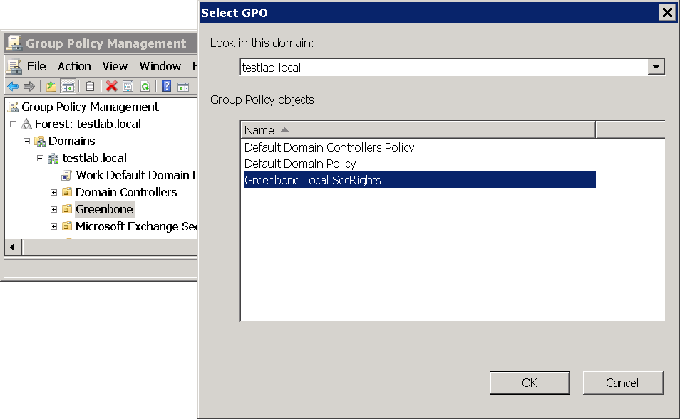
Creating a Group Policy Object (GPO)
In the left panel open the console Group Policy Management.
Right click Group Policy Objects and select New.
Enter
Greenbone Local SecRightsin the input box Name (see Fig. 5.15).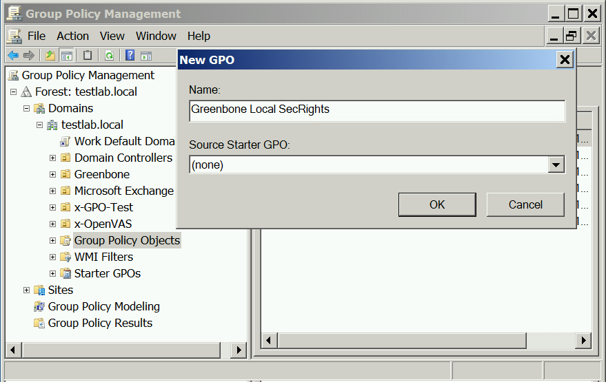
Fig. 5.15 Creating a new Microsoft Windows group policy object for Greenbone scans
Click OK.
Configuring the Policy
Click the policy Greenbone Local SecRights and select Edit.
Select Computer Configuration > Policies > Windows Settings > Security Settings in the left panel.
Click Restricted Groups and select Add Group.
Click Browse… and enter
Greenbone Local Scanin the input box (see Fig. 5.16).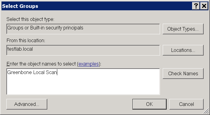
Fig. 5.16 Checking Microsoft Windows group names
Click Check Names.
Click OK twice to close the open windows.
At This group is member of click Add.
Enter
Administratorsin the input box Group (see Fig. 5.17) and click OK twice to close the open windows.Note
On non-English systems enter the respective name of the local administrator group.
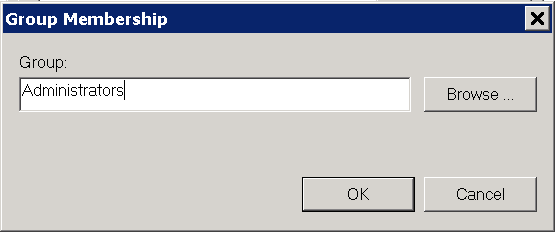
Fig. 5.17 Adding a group membership
Configuring the Policy to Deny the Group Greenbone Local Scan Logging into the System Locally
Click the policy Greenbone Local SecRights and select Edit.
Select Computer Configuration > Policies > Windows Settings > Security Settings > Local Policies > User Rights Assignment in the left panel.
In the right panel double click Deny log on locally.
Activate the checkbox Define these policy settings and click Add User or Group.
Click Browse… and enter
Greenbone Local Scanin the input box (see Fig. 5.18).Click Check Names.
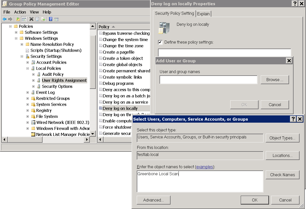
Fig. 5.18 Editing the policy
Click OK three times to close the open windows.
Configuring the Policy to Deny the Group Greenbone Local Scan Logging into the System Remotely
Click the policy Greenbone Local SecRights and select Edit.
Select Computer Configuration > Policies > Windows Settings > Security Settings > Local Policies > User Rights Assignment in the left panel.
In the right panel double click Deny log on through Desktop Services.
Activate the checkbox Define these policy settings and click Add User or Group.
Click Browse… and enter
Greenbone Local Scanin the input box (see Fig. 5.19).Click Check Names.
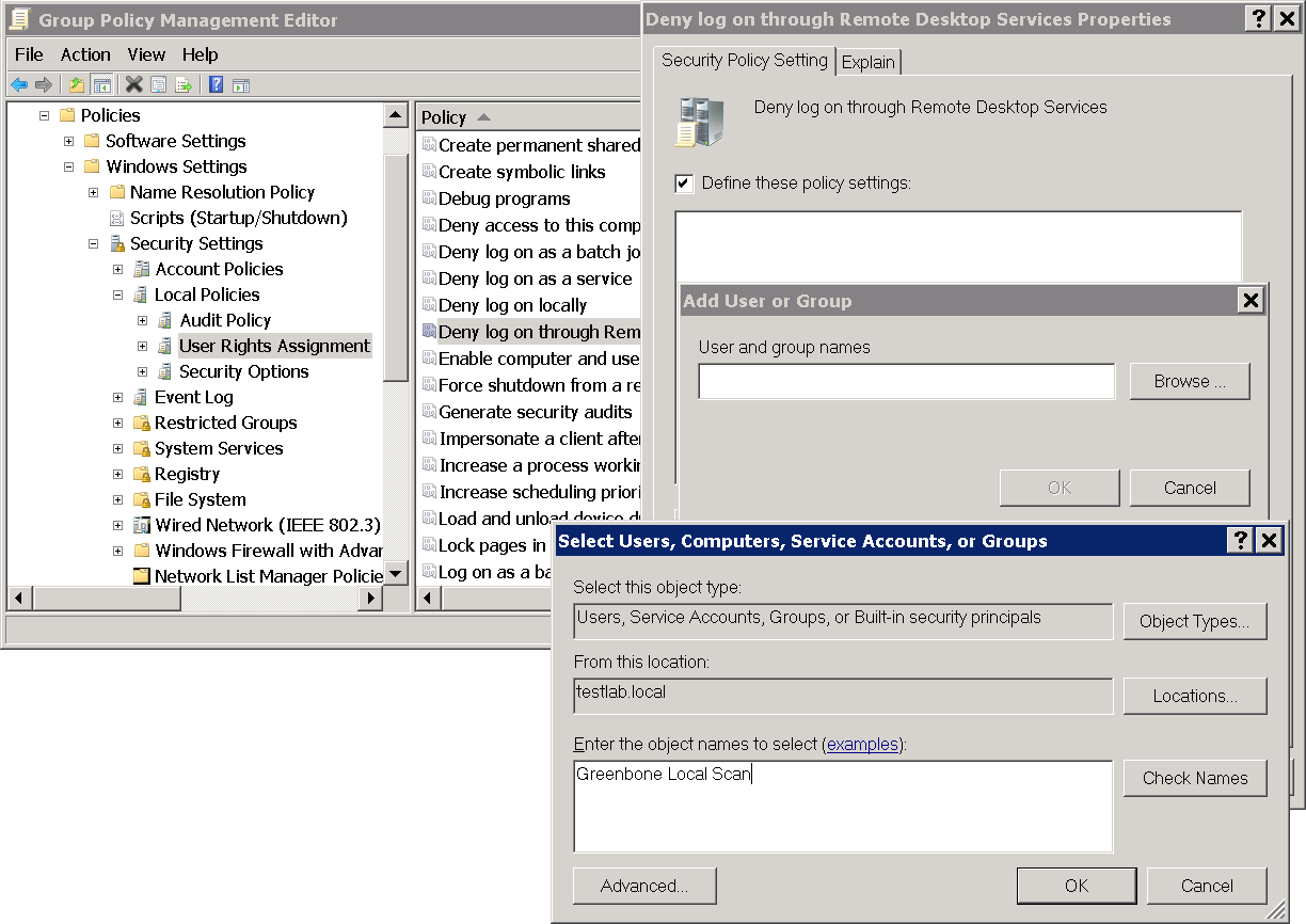
Fig. 5.19 Editing the policy
Click OK three times to close the open windows.
Configuring the Policy to Give Read Permissions Only to the Registry for the Group Greenbone Local Scan
Important
This setting still exists after the GPO has been removed (“tattooing GPO”).
This changes fundamental privileges which may not be simply reversed by removing the GPO.
Research whether the settings are compatible with the environment.
Note
The following steps are optional.
In the left panel right click Registry and select Add Key.
Select USERS and click OK (see Fig. 5.20).
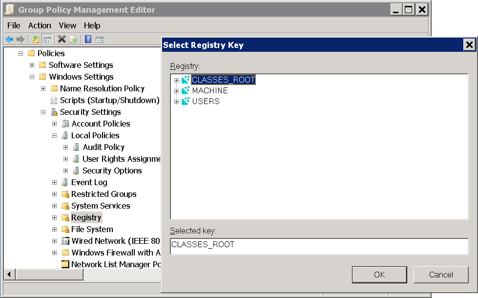
Fig. 5.20 Selecting the registry key
Click Advanced and Add.
Enter
Greenbone Local Scanin the input box and click OK (see Fig. 5.21).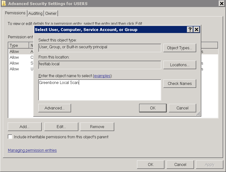
Fig. 5.21 Selecting the group Greenbone Local Scan
Select This object and child objects in the drop-down list Apply to.
Deactivate all checkboxes for Allow and activate the checkboxes Set Value, Create Subkey, Create Link, Delete, Change Permissions and Take Ownership for Deny (see Fig. 5.22).
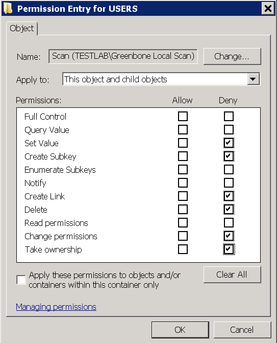
Fig. 5.22 Disallowing edition of the registry
Click OK twice and confirm the warning message by clicking Yes.
Click OK.
Select the radio buttons Configure this key then and Propagate inheritable permissions to all subkeys and click OK (see Fig. 5.23).
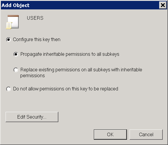
Fig. 5.23 Making the permissions recursive
Repeat the steps 2 to 9 for MACHINE and CLASSES_ROOT.
Linking the Group Policy Object
5.3.3.3 Restrictions
Based on the fact that write permissions to the registry and system drive have been removed, the following two tests will no longer work:
Leave information on scanned Windows hostsOID 1.3.6.1.4.1.25623.1.0.96171This test, if desired, creates information about the start and end of a scan under HKLM\Software\VulScanInfo. Due to denying write access to HKLM this is no longer possible. If the test should be possible, the GPO must be adjusted respectively.
Windows file ChecksumsOID 1.3.6.1.4.1.25623.1.0.96180This test, if desired, saves the tool ReHash under C:\Windows\system32 (for 32-bit systems) or C:\Windows\SysWOW64 (for 64-bit systems). Due to denying write access this is no longer possible. If the test should be possible, the tool must be saved separately or the GPO must be adjusted respectively.
5.3.3.4 Scanning Without Domain Administrator and Local Administrator Permissions
It is possible to build a GPO in which the user also does not have any local administrator permissions. But the effort to add respective read permissions to each registry branch and folder is huge. Unfortunately, inheriting of permissions is deactivated for many folders and branches. Additionally, these changes can be set by GPO but cannot be removed again (tattooing GPO). Specific permissions could be overwritten so that additional problems could occur as well.
Building a GPO in which the user does not have any local administrator permissions does not make sense from a technical and administrative point of view.
5.3.4 Requirements on Target Systems with Linux/Unix
For authenticated scans on Linux or Unix systems regular user access is usually enough. The login is performed via SSH. The authentication is done either with passwords or an SSH key stored on the Greenbone Cloud Service.
It needs to be made sure that public key authentication is not prohibited by the SSH daemon. The line
PubkeyAuthentication nomust not be present.Existing SSH keys may also be used. SSH keys can be generated with OpenSSH by using the command
ssh-keygenon Linux orputtygen.exeif using PuTTY on Microsoft Windows. The formats Ed25519 or RSA are recommended. All SSH keys must correspond to RFC 4716.For scans that include policy testing, root permission or the membership in specific groups (often
wheel) may be necessary. For security reasons many configuration files are only readable by super users or members of specific groups.
5.3.5 Requirements on Target Systems with ESXi
Note
If a vCenter Server Appliance (VCSA) is used to control ESXi hosts and users are created on the VCSA, they are only known on the VCSA and not on the ESXi hosts.
Scan users must be created on each ESXi host that will be scanned.
By default, local ESXi users are limited to read-only roles. Either an administrative account or a read-only role with permission to global settings has to be used.
A read-only role with permission to global settings can be set up as follows:
Open the web interface of the VMware ESXi instance and log in.
Select Host > Manage in the Navigator column on the left.
Select the register Security & users.
Select Roles in the left menu panel (see Fig. 5.25).
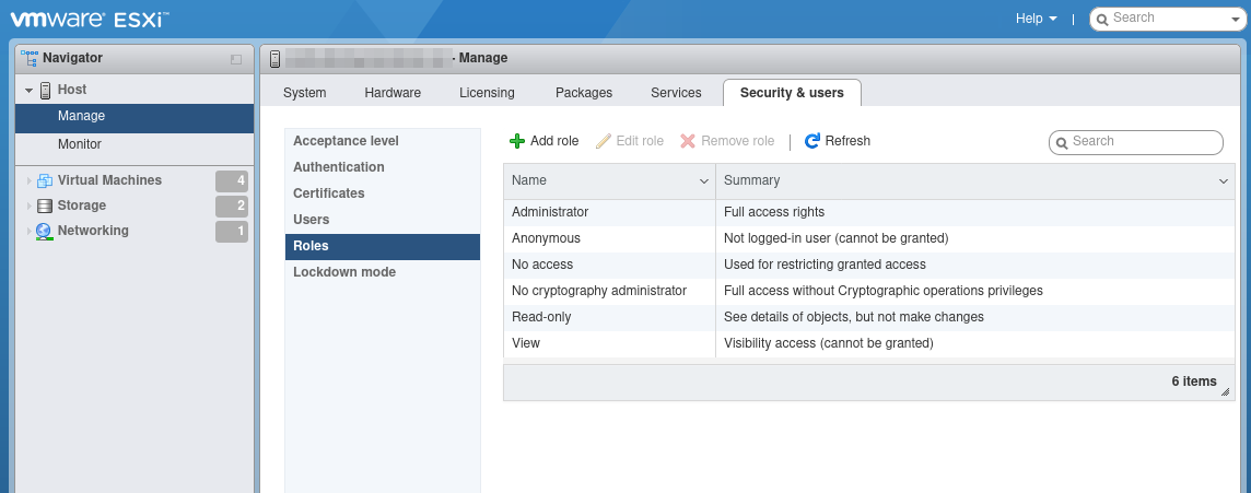
Fig. 5.25 Displaying the roles
Click Add role.
Enter a name for the role in the input box Role name.
Activate the checkbox System.
Click Global and activate the checkbox Settings (see Fig. 5.26).
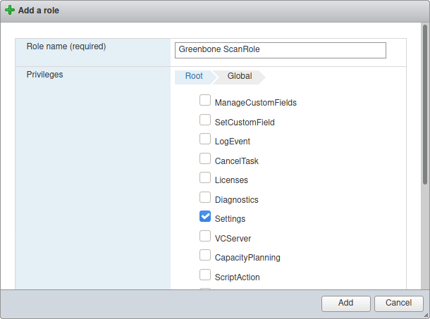
Fig. 5.26 Creating a role
Click Add.
Right click Host and select Permissions in the Navigator column on the left.
Select the scan user account used by the Greenbone Cloud Service.
Click Assign role.
Select the previously created role in the drop-down list (see Fig. 5.27).
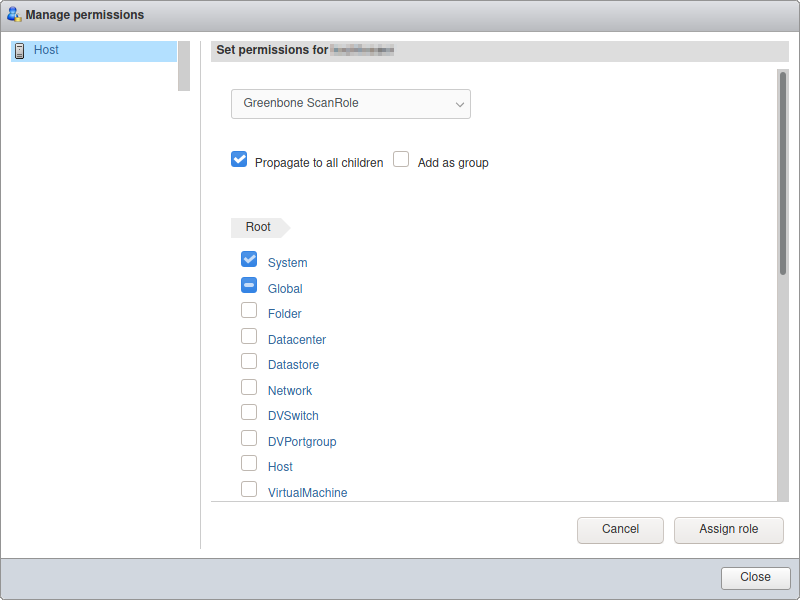
Fig. 5.27 Assigning the role to the scan user
Click Assign role.
Click Close.
5.3.6 Requirements on Target Systems with Cisco OS
The Greenbone Cloud Service can check network components like routers and switches for vulnerabilities as well. While the usual network services are discovered and checked via the network, some vulnerabilities can only be discovered by an authenticated scan. For the authenticated scan, the Greenbone Cloud Service can use SSH.
The Greenbone Cloud Service currently only requires the command show version to retrieve the current version of the firmware of the device.
To set up a less privileged user which is only able to run this command, several approaches are possible. The following example uses the role based access control feature.
Tip
Before using the following example, make sure all side effects of the configuration are understood. If used without verification the system may restrict further logins via SSH or console.
To use role based access control AAA and views have to be enabled:
> enable
# configure terminal
(config)# aaa new-model
(config)# exit
> enable view
# configure terminal
The following commands create a restricted view including just the command show version. The supplied password view-pw is not critical:
(config)# parser view gcs-view
(config-view)# secret 0 view-pw
(config-view)# commands exec include show version
(config-view)# exit
Now the user gcs-user with the password gcs-pw is created and linked to the view gcs-view:
(config)# username gcs-user view gcs-view password 0 gcs-pw
(config)# aaa authorization console
(config)# aaa authorization exec default local
If SSH is not enabled yet the following commands take care of that. Use the appropriate host name and domain:
(config)# hostname switch
(config)# ip domain-name greenbone.net
(config)# crypto key generate rsa general-keys modulus 2048
Finally, enable SSH logins using the following commands:
(config)# line vty 0 4
(config-line)# transport input ssh
(config-line)# Crtl-Z
The credentials of the user need to be entered on the platform. Select Login Credentials (category Scan Configuration) in the menu panel and create the appropriate user (see Chapter 5.3.2).
Link the credentials to the target to be used as SSH credentials.
5.4 Performing a Scheduled Scan
For continuous vulnerability management, the manual execution of task is tedious. The Greenbone Cloud Service supports the scheduling of tasks for their automation and refer to schedules as automatic scans at a specific time. They can be run once or repeatedly.
5.4.1 Creating a Schedule
A new schedule can be created as follows:
Select Schedules (category Scan Configuration) in the menu panel.
Create a new schedule by clicking + Create New Schedule.
Define the schedule (see Fig. 5.28).
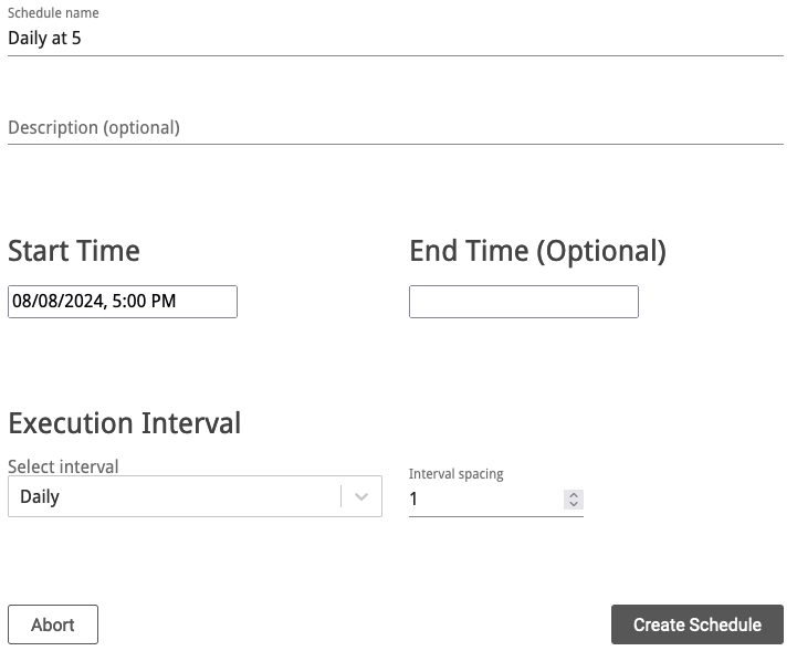
Fig. 5.28 Creating a new schedule
Click Create Schedule.
→ The schedule is created and can be selected when creating a new task (see Chapter 5.2.4).
The following details of the schedule can be defined:
- Schedule name
Definition of the name. The name can be chosen freely.
- Description (optional)
An optional comment can contain additional information.
- Start Time
Definition of the date and time for the first scan to start.
- End Time (Optional)
Definition of the date and time for the first scan to end.
By setting no end time, the scan runs indefinitely until it is finished.
- Execution Interval
Definition of the repetition rate of the task. It can be selected between Daily, Weekly and Monthly. Additionally, the space between intervals is set.
Example: a scheduled task with an interval of Weekly and an interval spacing of 2 runs every two weeks.
5.4.2 Managing Schedules
All existing schedules can be displayed by selecting Schedules (category Scan Configuration) in the menu panel.
For all schedules the following information is displayed:
- Name
Name of the schedule.
- Comment
Optional description of the schedule.
- Start Time
Start time of the first run of the task.
- End Time
Optional end time of the first run of the task.
- Interval Type
Time period between two runs of the task.
- Interval Spacing
Space between intervals.
For all schedules the following actions are available:
- Edit the schedule.
- Delete the schedule. Only schedules which are currently not used can be deleted.
5.5 Managing Targets
All existing targets can be displayed by selecting Targets (category Scan Configuration) in the menu panel.
Internal Targets
For all internal targets the following information is displayed:
- Name
Name of the target.
- Port list
Port list used if the target is used for a scan (see Chapter 5.2.4).
- IP Addresses
Number of scanned hosts.
For all targets the following actions are available:
 Open an overlay with detailed information about the target.
- Edit the target.
- Delete the target. Only targets which are currently not used can be deleted.
Clicking ![]() opens an overlay (see Fig. 5.29) containing the following information:
opens an overlay (see Fig. 5.29) containing the following information:
- Target name
Name of the target.
- Hosts
Hosts that are scanned if the target is used for a scan (see Chapter 5.2.4).
- Port list
Port list used if the target is used for a scan (see Chapter 5.2.4).
- Login Credentials
Credentials configured for the target.
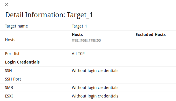
Fig. 5.29 Overlay containing information about the target
External Targets
For all external targets the following information is displayed:
- Name
Name of the target.
- Port list
Port list used if the target is used for a scan (see Chapter 5.2.4).
- Verified
Status of the validation of the configured hosts.
- IP Addresses
Number of scanned hosts.
For all targets the following actions are available:
- Open an overlay with detailed information about the target.
- Edit the target.
- Delete the target. Only targets which are currently not used can be deleted.
- Show pending host validations.
Clicking ![]() opens an overlay (see Fig. 5.29) containing the following information:
opens an overlay (see Fig. 5.29) containing the following information:
5.6 Managing Gateways
5.6.1 Page Gateways
All existing gateways can be displayed by selecting Gateways (category Scan Management) in the menu panel.
For all gateways the following information is displayed:
- Location
Textual description of the location of the gateway.
- Status
Status of the connection with the scanner.
- Description (optional)
Optional description of the gateway.
For all gateways the following actions are available:
- Edit the gateway.
- Delete the gateway.
5.6.2 Gateway Administration Menu (CLI)
Note
The gateway can be imported to Microsoft Hyper-V or VMware ESXi.
Network settings of the gateway are managed using the gateway administration menu:
Start the gateway in the virtual environment.
After the boot process is completed, log in to the gateway administration menu. The default login information is:
Login name:
adminPassword:
admin
→ Actions for the gateway are displayed (see Fig. 5.30).
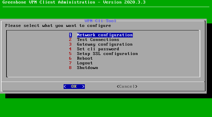
Fig. 5.30 Managing a gateway
The following actions are available:
- Network configuration
Set up the network of the gateway using DHCP or by entering IP address, netmask, DNS and gateway manually.
- Test connections
Check whether all gateway connections work as intended.
- Gateway configuration
Set the password for the gateway web interface and register the gateway.
- Set cli password
Set the password for the gateway administration menu (CLI)
- Setup SSL configuration
Set up a new SSL certificate.
- Reboot
Reboot the gateway.
- Logout
Log out from the gateway administration menu.
- Shutdown
Shut down the gateway.
5.6.3 Gateway Web Interface
Open the web browser and enter the following URL:
https://<ip>. Replace<ip>with the IP address of the gateway.Tip
The IP address can be displayed in the gateway administration menu by selecting Network configuration and pressing Enter (see Chapter 5.6.2).
Log in using the user name
adminand the password defined in the gateway administration menu (see Chapter 5.6.2).Select Overview in the menu panel to display the status and the ports of the gateway.
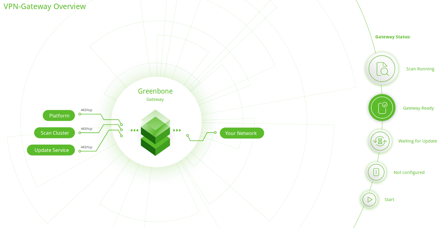
Fig. 5.31 Gateway overview
Select Settings in the menu panel.
→ The following actions are available:
Setting the API key of the gateway (see Chapter 5.2.3).
Setting the password for logging in to the gateway web interface.
Enabling/disabling error reporting.
5.7 Managing Tasks
All existing tasks can be displayed and managed on the pages Scan Management and Scan Configuration.
5.7.1 Page Scan Management
Select Scan Management in the menu panel.
For all tasks the following information is displayed:

Open the latest report of the scan. For reading, managing and downloading reports see Chapter 6.
- Task
Name of the task.
By clicking on the name of a task, an overlay with details is opened.
- Status
Current status of the task. The following status bars are possible:
 The task has not been run since it was created.
 The export of the task to the scan engine was requested.
 The task was successfully exported to the scan engine.
 The export of the task to the scan engine failed.
 The task was just started.
The Greenbone Cloud Service is preparing the scan.
The task was just started.
The Greenbone Cloud Service is preparing the scan. The scan is currently running.
The column Progress provides further details.
The scan is currently running.
The column Progress provides further details. The task was deleted.
The actual deletion process can take some time as reports need to be deleted as well.
The task was deleted.
The actual deletion process can take some time as reports need to be deleted as well. The task was requested to stop recently.
However, the scan engine has not yet reacted to this request yet.
The task was requested to stop recently.
However, the scan engine has not yet reacted to this request yet. The task was stopped.
The latest report is possibly not yet complete.
Other reasons for this status could be the reboot of the scan engine or a power outage.
After restarting the scanner, the task will be resumed automatically.
The task was stopped.
The latest report is possibly not yet complete.
Other reasons for this status could be the reboot of the scan engine or a power outage.
After restarting the scanner, the task will be resumed automatically. The task has been completed successfully.
 An error has occurred and the task was interrupted.
The latest report is possibly not complete yet or is missing completely.
An error has occurred and the task was interrupted.
The latest report is possibly not complete yet or is missing completely.- Progress
When the scan was started, further information about the scan status are displayed.
A percent value shows the completion of the scan based on the number of VTs executed on the selected hosts. For this reason, the value does not necessarily correlate with the time spent.
- Reports
Number of reports for the task. By clicking on the number, an overview of all reports is opened.
- Last Scan
Date and time of the last scan of the task.
- Target
Scan target that is examined when the task is run.
By clicking on the name of a target, an overlay with details is opened.
- Executive PDF
By clicking
 the “Executive Report” can be downloaded.
It contains general information about the scan and lists of hosts sorted by severity.
the “Executive Report” can be downloaded.
It contains general information about the scan and lists of hosts sorted by severity.- Technical PDF
By clicking
the “Technical Report” can be downloaded.
It contains general information about the scan as well as about the scanned hosts and details for each found vulnerability.
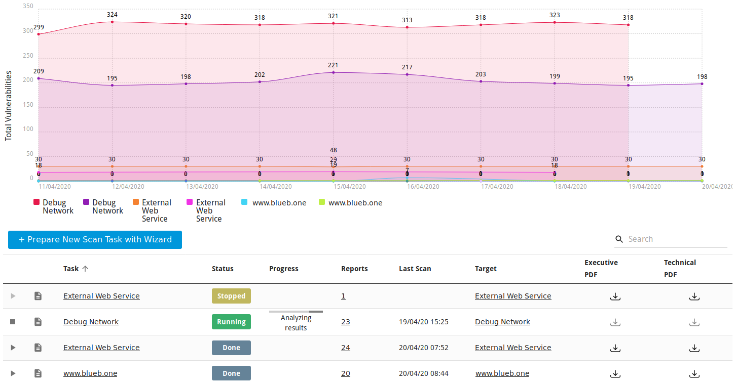
Fig. 5.32 Page Scan Management
5.7.2 Page Scan Configuration
Select Scan Configuration in the menu panel.
For all tasks the following information is displayed:
- Name
Name of the task.
- Type
Type of the target: internal or external.
- Scan Target
Scan target that is examined when the task is run.
By clicking on the name of a target, an overlay providing details is opened.
- Scan Configuration
Scan configuration that is used for the task.
- Schedule
Schedule for this task (see Chapter 5.4).
By clicking on the name of a schedule, an overlay providing details is opened.
For all targets the following actions are available:
- Edit the target.
- Delete the target. Only targets which are currently not used can be deleted.
5.8 Scan Configurations
The scan configuration specifies which vulnerability tests are performed during a scan. The Greenbone Cloud Service comes with various predefined scan configurations.
The following configurations are available:
- Discovery
This scan configuration only uses VTs that provide information about the target system. No vulnerabilities are being detected.
Amongst others, the collected information contains information about open ports, used hardware, firewalls, used services, installed software and certificates. The system is inventoried completely.
The VT families are dynamic, which means that new VTs of the chosen VT families are added and used automatically.
- Host Discovery
This scan configuration is used to detect target systems. No vulnerabilities are being detected.
The used port scanner is Ping Host which detects whether a host is alive.
The VT families are dynamic, which means that new VTs of the chosen VT families are added and used automatically.
- System Discovery
This scan configuration is used to detect target systems including installed operating systems and used hardware. No vulnerabilities are being detected.
The used port scanners are Ping Host and Nmap which detect whether a host is alive.
The VT families are dynamic, which means that new VTs of the chosen VT families are added and used automatically.
- Analysis [standard]
For many environments this is one of the best options to start with.
This scan configuration is based on the information gathered in the previous port scan and uses almost all VTs. Only VTs that will not damage the target system are used. VTs are optimized in the best possible way to keep the potential false negative rate especially low. The other configurations only provide more value in rare cases but with much higher effort.
The VT families are dynamic, which means that new VTs of the chosen VT families are added and used automatically.
- Analysis [aggressive]
This scan configuration expands the scan configuration Analyze [Standard] with VTs that could disrupt services or systems or even cause shutdowns.
The VT families are dynamic, which means that new VTs of the chosen VT families are added and used automatically.
This scan configuration may not always be absolutely reliable depending on environmental conditions, which may be reflected in an increased false-positive rate. Narrowing down the suspected false-positive edge cases may require manual analysis.
- Analyse [standard] without Brute force attacks and Default Accounts
For many environments this is one of the best options to start with.
This scan configuration is based on the information gathered in the previous port scan and uses almost all VTs. Only VTs that will not damage the target system are used. VTs are optimized in the best possible way to keep the potential false-negative rate especially low.
The VT families are dynamic, which means that new VTs of the chosen VT families are added and used automatically.
5.9 Port Lists
The port list configured for a target has a large impact on the duration of the alive test and the vulnerability scan of this target.
Ports are the connection points of network communication. Each port of a system connects with the port on another system.
Transmission Control Protocol (TCP) ports
65535 TCP ports for each system
Data transmission occurs in both directions between two TCP ports.
The scan of TCP ports is usually performed simply and fast.
User Datagram Protocol (UDP) ports
65535 UDP ports for each system
Data transmission occurs only in one directions between two UDP ports.
Data received by UDP are not necessarily confirmed, so the testing of UDP ports usually takes longer.
Ports 0 to 1023 are privileged or system ports and cannot be opened by user applications [1].
The Internet Assigned Numbers Authority (IANA) assigns ports to standard protocols, for example port 80 to “http” or port 443 to “https”. Over 5000 ports are registered.
Scanning all ports takes too long in many cases and many ports are usually not used. To overcome this, port lists can be used.
All ports of all systems of all internet accessible systems were analyzed and lists of the most used ports were created. Those do not necessarily reflect the IANA list because there is no obligation to register a specific service type for a respective port. Nmap, an open source port scanner, and the OpenVAS scanner use different lists by default and do not check all ports either.
For most scans it is often enough to scan the ports registered with the IANA.
The following port lists are predefined on the Greenbone Cloud Service:
All IANA assigned TCP: all TCP ports assigned by IANA
All privileged TCP
All privileged TCP and UDP
All TCP
OpenVAS Default: the TCP ports which are scanned by the OpenVAS scanner when passing the default port range preference
All IANA assigned TCP and UDP: all TCP and UDP ports assigned by IANA
All TCP and Nmap 5.51 top 100 UDP: all TCP ports and the top 100 UDP ports according to Nmap 5.51
All TCP and Nmap 5.51 top 1000 UDP: all TCP ports and the top 1000 UDP ports according to Nmap 5.51
Nmap 5.51 top 2000 TCP and top 100 UDP: the top 2000 TCP ports and the top 100 UDP ports according to Nmap 5.51
Web services
5.10 Using Notifications
The user can receive summaries about the configured scans and alerts for completed scans (see Chapter 4.2).
5.11 Obstacles While Scanning
There are several typical problems which might occur during a scan using the default values of the Greenbone Cloud Service. While the default values are valid for most environments and customers, depending on the actual environment and the configuration of the scanned hosts they might require some tweaking.
5.11.1 Hosts not Found
During a typical scan (either Discovery or Analysis [Standard]) the scanner will first use the ping command to check the availability of the configured targets by default. If the target does not reply to the ping request it is presumed to be dead and will not be scanned by the port scanner or any VT.
In most LAN environments this does not pose any problems because all devices will respond to a ping request. But sometimes (local) firewalls or other configuration might suppress the ping response. If this happens, the target will not be scanned and will not be included in the results and the scan report.
To remediate this problem, both the target configuration and the scan configuration support the setting of the alive test (see Chapter 5.2.1).
If the target does not respond to a ping request, a TCP ping may be tested.
5.11.2 Long Scan Periods
Once the target is discovered to be alive using the ping command, the scanner uses a port scanner to scan the target. By default, a TCP port list containing around 5000 ports is used. If the target is protected by a (local) firewall dropping most of these packets the port scan will need to wait for the timeout of each individual port. If the hosts are protected by (local) firewalls the port lists or the firewalls may be tuned. If the firewall does not drop the request but rejects the request the port scanner does not have to wait for the timeout. This is especially true if UDP ports are included in the scan.
Footnotes