
10. Scanning a System
Note
This chapter documents all possible menu options.
However, not all GSM types support all of these menu options. Check the tables in Chapter 3 to see whether a specific feature is available for the used GSM type.
10.1. Using the Task Wizard for a First Scan
The task wizard can configure and start a basic scan with minimal user input.
10.1.1. Using the Task Wizard
When logging into the web interface of the GSM appliance for the first time after initial set up an empty dashboard will be displayed (see Fig. 10.1).
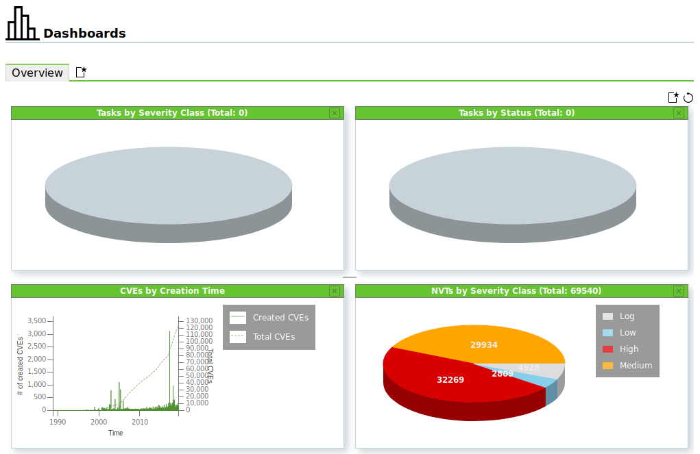
Fig. 10.1 Empty default dashboard
A new task with the task wizard can be configured as follows:
Select Scans > Tasks in the menu bar.
Start the wizard by moving the mouse over
 and clicking Task Wizard.
Enter the IP address or host name of the target system in the input box (see Fig. 10.2).
Note
If using a DNS name however, the GSM has to be able to resolve the name.
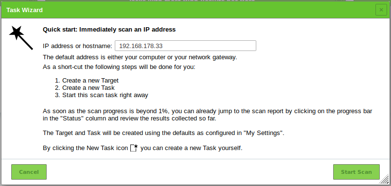
Fig. 10.2 Configuring the task wizard
Click Start Scan.
→ The task wizard performs the following steps automatically:
- Creating a new scan target on the GSM.
- Creating a new scan task on the GSM.
- Starting the scan task immediately.
- Displaying the page Tasks.
After the task is started, the progress can be monitored (see Fig. 10.3).
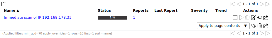
Fig. 10.3 Page Tasks displaying the progress of the task
For the status of a task see Chapter 10.8.
Tip
The report of a task can be displayed as soon as the task has been started by clicking the bar in the column Status. For reading, managing and downloading reports see Chapter 11.
As soon as the status changes to Done the complete report is available. At any the time the intermediate results can be reviewed (see Chapter 11.2.1).
Note
It can take a while for the scan to complete. The page is refreshing automatically if new data is available.
10.1.2. Using the Advanced Task Wizard
Next to the simple wizard the GSM also provides an advanced wizard that allows for more configuration options.
A new task with the advanced task wizard can be configured as follows:
Select Scans > Tasks in the menu bar.
Start the wizard by moving the mouse over
and clicking Advanced Task Wizard.Define the task (see Fig. 10.4).
Tip
For the information to enter in the input boxes see Chapters 10.2.1 and 10.2.2.
If an e-mail address is entered in the input box Email report to an alert is created sending an e-mail as soon as the task is completed (see Chapter 10.12).
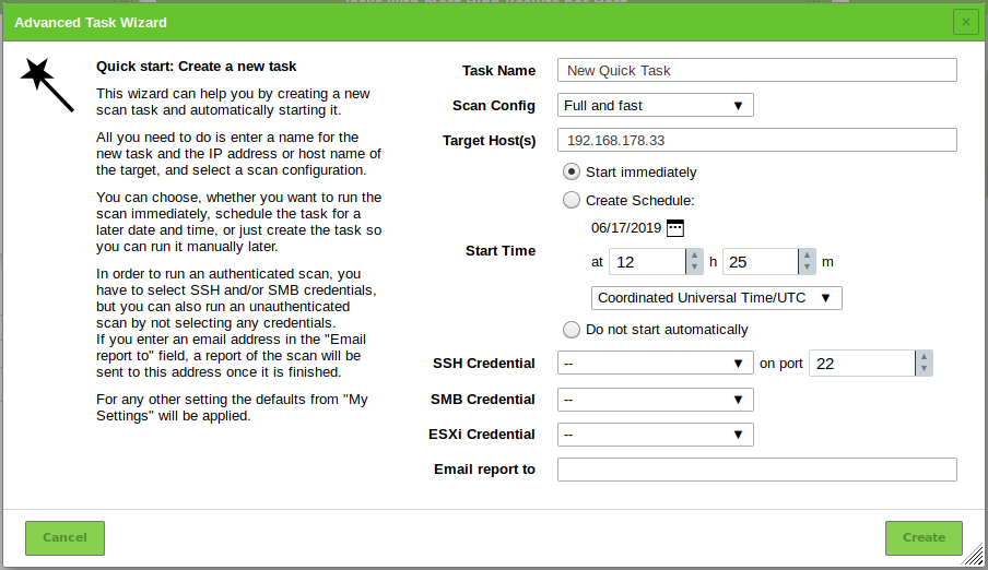
Fig. 10.4 Configuring the advanced task wizard
Click Create.
→ The advanced task wizard performs the following steps automatically:
- Starting the scan task immediately.
- Displaying the page Tasks.
For the status of a task see Chapter 10.8.
Tip
The report of a task can be displayed as soon as the task has been started by clicking the bar in the column Status. For reading, managing and downloading reports see Chapter 11.
As soon as the status changes to Done the complete report is available. At any the time the intermediate results can be reviewed (see Chapter 11.2.1).
Note
It can take a while for the scan to complete. The page is refreshing automatically if new data is available.
10.1.3. Using the Wizard to Modify a Task
An additional wizard can modify an existing task:
Select Scans > Tasks in the menu bar.
Start the wizard by moving the mouse over
and clicking Modify Task Wizard.Select the task which should be modified in the drop-down-list Task (see Fig. 10.5).
Create a schedule for the task by selecting the radiobutton Create Schedule (see Chapter 10.10).
The date of the first scan can be selected by clicking
 and the time can be set using the input boxes.
Enter the e-mail address to which the report should be sent in the input box Email report to.
Click Modify Task.
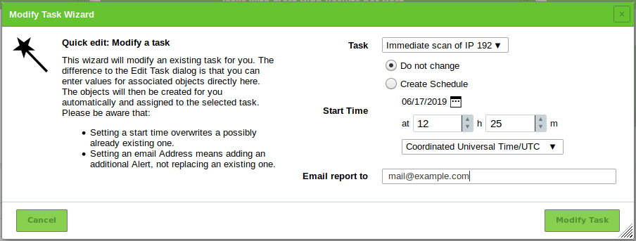
Fig. 10.5 Modifying a task using the wizard
10.2. Configuring a Simple Scan Manually
Generally speaking the GSM can use two different approaches to scan a target:
- Simple scan
- Authenticated scan using local security checks
![]() The steps of a simple scan are explained in a video based on GOS 3.1 at https://docs.greenbone.net/Videos/gos-3.1/en/GSM-FirstScan-GOS-3.1-en-20150716.mp4.
The steps of a simple scan are explained in a video based on GOS 3.1 at https://docs.greenbone.net/Videos/gos-3.1/en/GSM-FirstScan-GOS-3.1-en-20150716.mp4.
The following steps have to be executed to configure a simple scan:
- Creating a target
- Creating a task
- Running the task
10.2.1. Creating a Target
The first step is to define a scan target as follows:
Select Configuration > Targets in the menu bar.
Create a new target by clicking
 .
.Define the target (see Fig. 10.6).
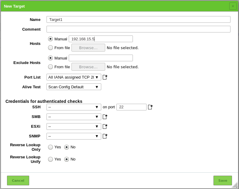
Fig. 10.6 Creating a new target
Click Save.
The following information can be entered:
- Name
- The name can be chosen freely. A descriptive name should be chosen if possible. Possibilities are Mailserver, ClientNetwork, Webserverfarm, DMZ or describing the entered systems in more detail.
- Comment
- The optional comment allows specifying background information. It simplifies understanding the configured targets later.
- Hosts
Manual entry of the hosts that should be scanned, separated by commas, or importing a list of hosts.
Note
The IP address or the host name is required. In both cases it is necessary that the GSM can connect to the system. If using the host name, the GSM must also be able to resolve the name.
When entering manually the following options are available:
- Single IP address, e.g. 192.168.15.5
- Host name, e.g. mail.example.com
- IPv4 address range in long format, e.g. 192.168.15.5-192.168.15.27
- IPv4 address range in short format, e.g. 192.168.55.5-27
- IPv4 address range in CIDR notation, e.g. 192.168.15.0/24 1 (at most 4096 IP addresses)
- Single IPv6 address, e.g. fe80::222:64ff:fe76:4cea
- IPv6 address range in long format, e.g. ::12:fe5:fb50-::12:fe6:100
- IPv6 address range in short format, e.g. ::13:fe5:fb50-fb80
- IPv6 address range in CIDR notation, e.g. fe80::222:64ff:fe76:4cea/120 (at most 4096 IP addresses)
Multiple options can be mixed. If importing from a file, the same syntax can be used. Entries can be separated with commas or by line breaks. If many systems have to be scanned, using a file with the hosts is simpler than entering all hosts manually. The file should use UTF-8 text encoding.
Alternatively the systems can be imported from the host asset database.
Note
Importing a host from the asset database is only possible if a target is created from the page Hosts (see Chapter 12.1.3).
- Exclude Hosts
Manual entry of the hosts that should be excluded from the list mentioned above, separated by commas, or importing a list of hosts.
The same specifications as for Hosts apply.
- Port list
Port list used for the scan (see Chapter 10.7).
Note
A port list can be created on the fly by clicking
next to the drop-down-list.
- Alive Test
This options specifies the method to check if a target is reachable. Options are:
- Scan Config Default (uses alive test method(s) configured in the NVT Ping Host (OID: 1.3.6.1.4.1.25623.1.0.100315) of the NVT family Port scanners)
- ICMP Ping
- TCP-ACK Service Ping
- TCP-SYN Service Ping
- ARP Ping
- ICMP & TCP-ACK Service Ping
- ICMP & ARP Ping
- TCP-ACK Service & ARP Ping
- ICMP, TCP-ACK Service & ARP Ping
- Consider Alive
Sometimes there are problems with this test from time to time. In some environments routers and firewall systems respond to a TCP service ping with a TCP-RST even though the host is actually not alive (see Chapter 10.13).
Network components exist that support Proxy-ARP and respond to an ARP ping. Therefore this test often requires local customization to the environment.
- SSH Credential
- Selection of a user that can log into the target system of a scan if it is a Linux or Unix system. This allows for an authenticated scan using local security checks (see Chapters 10.3.2 and 10.3).
- SMB Credential
- Selection of a user that can log into the target system of a scan if it is a Microsoft Windows system. This allows for an authenticated scan using local security checks (see Chapters 10.3.2 and 10.3).
- ESXi Credential
- Selection of a user that can log into the target system of a scan if it is a VMware ESXi system. This allows for an authenticated scan using local security checks (see Chapters 10.3.2 and 10.3).
- SNMP Credential
Selection of a user that can log into the target system of a scan if it is an SNMP aware system. This allows for an authenticated scan using local security checks (see Chapters 10.3.2 and 10.3).
Note
All credentials can be created on the fly by clicking
next to the credential.- Reverse Lookup Only
- Only scan IP addresses that can be resolved into a DNS name.
- Reverse Lookup Unify
If multiple IP addresses resolve to the same DNS name the DNS name will only get scanned once.
Note
For reverse lookup unify, all target addresses are checked prior to the scan in order to reduce the number of actual scanned addresses. For large targets and for networks in which reverse lookup causes delays, this leads to a long phase where the task remains at 1 % progress.
This option is not recommended for large networks or networks in which reverse lookups cause delays.
10.2.2. Creating a Task
The second step is to create a task.
The GSM controls the execution of a scan using tasks. These tasks can be repeated regularly or run at specific times (see Chapter 10.10).
A task can be created as follows:
Select Scans > Tasks in the menu bar.
Create a new task by moving the mouse over
and clicking New Task.Define the task (see Fig. 10.7).
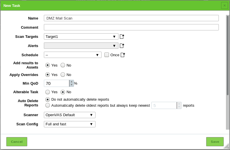
Fig. 10.7 Creating a new task
Click Save.
→ The task is created and displayed on the page Tasks.
The following information can be entered:
- Name
- The name can be chosen freely. A descriptive name should be chosen if possible. Possibilities are Mailserver, ClientNetwork, Webserverfarm, DMZ or describing the entered systems in more detail.
- Comment
- The optional comment allows for the entry of background information. It simplifies understanding the configured task later.
- Scan Targets
Select a previously configured target from the drop-down-list (see Chapter 10.2.1).
Additionally, the target can be created on the fly by clicking
next to the drop-down-list.- Alerts
Select a previously configured alert from the drop-down-list (see Chapter 10.12). Status changes of a task can be communicated via e-mail, Syslog, HTTP or a connector.
Additionally, an alert can be created on the fly by clicking
next to drop-down-list.- Schedule
Select a previously configured schedule from the drop-down-list (see Chapter 10.10). The task can be run once or repeatedly at a predetermined time, e.g. every Monday morning at 6:00 am.
Additionally, a schedule can be created on the fly by clicking
next to the drop-down-list.- Add results to Asset Management
- Selecting this option will make the systems available to the asset management of the GSM automatically (see Chapter 12). This selection can be changed at a later point as well.
- Apply Overrides
- Overrides can be directly applied when adding the results to the asset database (see Chapter 11.8).
- Min QoD
- Here the minimum quality of detection can be specified for the addition of the results to the asset database.
- Alterable Task
- Allow for modification of the task even though reports were already created. The consistency between reports can no longer be guaranteed if tasks are altered.
- Auto Delete Reports
- This option may automatically delete old reports. The maximum number of reports to store can be configured. If the maximum is exceeded, the oldest report is automatically deleted. The factory setting is Do not automatically delete reports.
- Scanner
- By default, only the built-in OpenVAS and CVE scanners are supported (see Chapter 10.11). Sensors can be used as additional scanning engines but need to be configured first (see Chapter 16).
Note
The following options are only relevant for the OpenVAS scanner. The CVE scanner does not support any options.
- Scan Config
- The GSM comes by default with seven pre-configured scan configurations for the OpenVAS scanner (see Chapter 10.9).
- Network Source Interface
- Here a source interface name can be entered to tag the scan with the interface. Only users which are allowed to access this interface are able to use and run the scan. This setting has no impact on the actual routing of the scan. The routing can only be influenced by configuring the network settings (see Chapter 7.2.2).
- Order for target hosts
Select how the specified network area should be searched. Options available are:
- Sequential
- Random
- Reverse
This is interesting if for example a network, e.g. 192.168.0.0/24, is scanned that has lots of systems at the beginning or end of the IP address range. With the selection of the Random mode the progress view is more meaningful.
- Maximum concurrently executed NVTs per host/Maximum concurrently scanned hosts
- Select the speed of the scan on one host. The default values are chosen sensibly. If more NVTs run simultaneously on a system or more systems are scanned at the same time, the scan may have a negative impact on either the performance of the scanned systems, the network or the GSM appliance itself. These values “maxhosts” and “maxchecks” may be tweaked.
10.2.3. Starting the Task
In the row of the newly created task click  .
.
Note
For scheduled task  is displayed. The task is starting at the time that was defined in the schedule (see Chapter 10.10).
→ The scan is running. For the status of a task see Chapter 10.8.
Tip
The report of a task can be displayed as soon as the task has been started by clicking the bar in the column Status. For reading, managing and downloading reports see Chapter 11.
As soon as the status changes to Done the complete report is available. At any the time the intermediate results can be reviewed (see Chapter 11.2.1).
Note
It can take a while for the scan to complete. The page is refreshing automatically if new data is available.
10.3. Configuring an Authenticated Scan Using Local Security Checks
An authenticated scan can provide more vulnerability details on the scanned system. During an authenticated scan the target is both scanned from the outside using the network and from the inside using a valid user login.
During an authenticated scan the GSM logs into the target system in order to run local security checks (LSC). The scan requires the prior setup of user credentials. These credentials are used to authenticate to different services on the target system. In some circumstances the results could be limited by the permissions of the users used.
The NVTs in the corresponding NVT families (local security checks) will only be executed if the GSM was able to log into the target system. The local security check NVTs in the resulting scan are minimally invasive.
The GSM only determines the risk level but does not introduce any changes on the target system. However, the login by the GSM is probably logged in the protocols of the target system.
The GSM can use different credentials based on the nature of the target. The most important ones are:
- SMB
- On Microsoft Windows systems the GSM can check the patch level and locally installed software such as Adobe Acrobat Reader or the Java suite.
- SSH
- This access is used to check the patch level on Unix and Linux systems.
- ESXi
- This access is used for testing of VMware ESXi servers locally.
- SNMP
- Network components like routers and switches can be tested via SNMP.
10.3.1. Advantages and Disadvantages of Authenticated Scans
The extent and success of the testing routines for authenticated scans depend heavily on the permissions of the used account.
On Linux systems an unprivileged user is sufficient and can access most interesting information while especially on Microsoft Windows systems unprivileged users are very restricted and administrative users provide more results.
An unprivileged user does not have access to the Microsoft Windows registry and the Microsoft Windows system folder \windows which contains the information on updates and patch levels.
Local security checks are the most gentle method to scan for vulnerability details. While remote security checks try to be least invasive as well, they may have some impact.
Simply stated an authenticated scan is similar to a Whitebox approach. The GSM has access to prior information and can access the target from within. Especially the registry, software versions and patch levels are accessible.
A remote scan is similar to a Blackbox approach. The GSM uses the same techniques and protocols as a potential attacker to access the target from the outside. The only information available was collected by the GSM itself. During the test the GSM may provoke malfunctions to extract any available information on the used software, e.g. the scanner may send a malformed request to a service to trigger a response containing further information on the deployed product.
During a remote scan using the scan configuration Full and fast all remote checks are safe.
The used NVTs may have some invasive components but none of the used NVTs try to trigger a defect or malfunction in the target (see example below).
This is ensured by the scan preference safe_checks=yes in the scan configuration (see Chapter 10.9.5).
All NVTs with very invasive components or which may trigger a denial of service (DoS) are automatically excluded from the test.
Example for an Invasive NVT
An example for an invasive but safe NVT is the Heartbleed NVT. It is executed even with safe_checks enabled because the NVT does not have any negative impact on the target.
The NVT is still invasive because it tests the memory leakage of the target. If the target is vulnerable, actual memory of the target is leaked. The GSM does not evaluate the leaked information. The information is immediately discarded.
10.3.2. Using Credentials
Credentials for local security checks are required to allow NVTs to log into target systems, e.g. for the purpose of locally checking the presence of all vendor security patches.
10.3.2.1. Creating a Credential
A new credential can be created as follows:
Select Configuration > Credentials in the menu bar.
Create a new credential by clicking
.Define the credential (see Fig. 10.8).
Click Save.
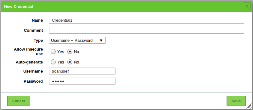
Fig. 10.8 Creating a new credential
The following details of the credential can be defined:
Note
If the details contain German umlauts, the login does not work. The umlauts have to be replaced as follows:
- “ß” → “ss”
- “ä” → “a”
- “ö” → “o”
- “ü” → “u”
- Name
- Definition of the name. The name can be chosen freely.
- Comment
- An optional comment can contain additional information.
- Type
Definition of the credential type. The following types are possible:
- Username + Password
- Username + SSH Key
- Client Certificate
- SNMP
- S/MIME Certificate
- PGP Encryption Key
- Password only
- Allow insecure use
- Select whether the GSM can use the credential for unencrypted or otherwise insecure authentication methods.
Depending on the selected type further options are shown:
- Username + Password
- Auto-generate
Select whether the GSM creates a random password.
Note
If the radiobutton Yes is selected, it is not possible to define a password in the input box Password.
- Username
Definition of the login name used by the GSM to authenticate on the scanned target system.
- Password
Definition of the password used by the GSM to authenticate on the scanned target system.
- Username + SSH Key
- Auto-generate
Select whether the GSM creates a random password.
Note
If the radiobutton Yes is selected, it is not possible to define a password in the input box Password.
- Username
Definition of the login name used by the GSM to authenticate on the scanned target system.
- Passphrase
Definition of the passphrase of the private SSH key.
- Private Key
Upload of the private SSH key.
- Client Certificate
- Passphrase
- Definition of the passphrase of the private SSH key.
- Certificate
- Upload of the certificate file.
- Private Key
- Upload of the corresponding private key.
- SNMP
- SNMP Community
- Definition of the community for SNMPv1 or SNMPv2c.
- Username
- Definition of the user name for SNMPv3.
- Password
- Definition of the password for SNMPv3.
- Privacy Password
- Definition of the password for the encryption for SNMPv3.
- Auth Algorithm
- Selection of the authentication algorithm (MD5 or SHA1).
- Privacy Algorithm
- Selection of the encryption algorithm (AES, DES or none).
- S/MIME Certificate
- S/MIME Certificate
- Upload of the certificate file.
- PGP Encryption Key
- PGP Public Key
- Upload of the key file.
- Password only
- Password
- Definition of the password used by the GSM to authenticate on the scanned target system.
Note
The credential has to be linked to at least one target. This allows the scan engine to apply the credential.
10.3.2.2. Managing Credentials
List Page
All existing credentials can be displayed by selecting Configuration > Credentials in the menu bar.
For all credentials the following information is displayed:
- Name
- Name of the credential.
- Type
- Chosen credential type.
- Allow insecure use
- Indication whether the GSM can use the credential for unencrypted or otherwise insecure authentication methods.
- Login
- User name for the credential if a credential type that requires a user name is chosen.
For all credentials the following actions are available:
 Delete the credential. Only credentials which are currently not used can be deleted.
 Edit the credential.
 Clone the credential.
 Export the credential as an XML file.
Depending on the chosen credential type (see Chapter 10.3.2.1) more actions may be available:
 Download an EXE package for Microsoft Windows. This action is available if Username + Password was chosen.
 Download an RPM package for Red Hat Enterprise Linux and its derivates. This action is available if Username + SSH Key was chosen.
 Download a Debian package for Debian GNU/Linux and its derivates. This action is available if Username + SSH Key was chosen.
 Download a public key. This action is available if Username + SSH Key or Client Certificate was chosen.
These installation packages simplify the installation and creation of accounts for authenticated scans. They create the user and the most important permissions for the authenticated scan and reset them during uninstalling.
Note
If the auto-generation of passwords is enabled (see Chapter 10.3.2.1), the packages have to be used, otherwise the usage is optional.
Note
By clicking or below the list of credentials more than one credential can be deleted or exported at a time. The drop-down-list is used to select which credentials are deleted or exported.
Details Page
Click on the name of a credential to display the details of the credential. Click  to open the details page of the credential.
The following registers are available:
- Information
- General information about the credential.
- User Tags
- Assigned tags (see Chapter 8.5).
- Permissions
- Assigned permissions (see Chapter 9.4).
The following actions are available in the upper left corner:
 Open the corresponding chapter of the user manual.
 Show the list page of all credentials.
- Create a new credential (see Chapter 10.3.2.1).
- Clone the credential.
- Edit the credential.
- Delete the credential. Only credentials which are currently not used can be deleted.
- Export the credential as an XML file.
Depending on the chosen credential type (see Chapter 10.3.2.1) more actions may be available:
- Download an EXE package for Microsoft Windows. This action is available if Username + Password was chosen.
- Download an RPM package for Red Hat Enterprise Linux and its derivates. This action is available if Username + SSH Key was chosen.
- Download a Debian package for Debian GNU/Linux and its derivates. This action is available if Username + SSH Key was chosen.
- Download a public key. This action is available if Username + SSH Key or Client Certificate was chosen.
10.3.3. Requirements on Target Systems with Microsoft Windows
10.3.3.1. General Notes on the Configuration
The remote registry service must be started in order to access the registry.
This is achieved by configuring the service to automatically start up. If an automatic start is not preferred, a manual startup can be configured. In that case the service is started while the system is scanned by the GSM and afterwards it is disabled again. To ensure this behaviour the following information about LocalAccountTokenFilterPolicy must be considered.
It is necessary that for all scanned systems the file and printer sharing is activated. If using Microsoft Windows XP, take care to disable the setting Use Simple File Sharing.
For individual systems not attached to a domain the following registry key must be set:
HKLM\SOFTWARE\Microsoft\Windows\CurrentVersion\Policies\System\
DWORD: LocalAccountTokenFilterPolicy = 1
On systems with domain controller the user account in use must be a member of the group Domain Administrators to achieve the best possible results. Due to the permission concept it is not possible to discover all vulnerabilities using the Local Administrator or the administrators assigned by the domain. Alternatively follow the instructions in Chapter 10.3.3.2.
Should a Local Administrator be selected – which it explicitly not recommended – it is mandatory to set the following registry key as well:
HKLM\SOFTWARE\Microsoft\Windows\CurrentVersion\Policies\System\
DWORD: LocalAccountTokenFilterPolicy = 1
Generated install package for credentials: The installer sets the remote registry service to auto start. If the installer is executed on a domain controller, the user account will be assigned to the group BUILTIN/Administrators (
SID S-1-5-32-544).An exception rule for the GSM on the Microsoft Windows firewall must be created. Additionally, on XP systems the service File and Printer Sharing must be set to enabled.
Generated install package for credentials: During the installation the installer offers a dialog to enter the IP address of the GSM. If the entry is confirmed, the firewall rule is configured. The service File and Printer Sharing will be enabled in the firewall rules.
10.3.3.2. Configuring a Domain Account for Authenticated Scans
For authenticated scans of Microsoft Windows target systems, it is highly recommended to use a domain account with a domain policy that grants local administrator privileges. This has several advantages:
- A domain policy only needs to be created once and can then be applied or revoked for different user accounts.
- Editing the Microsoft Windows registry locally is no longer required. User administration is thus centralized, which saves time in the long term and reduces possible configuration errors.
- From a vulnerability assessment perspective, only a domain account allows for the detection of domain-related scan results. These results will be missing if using a local user account.
- There are also several security advantages to using a domain account with the domain policy recommended by Greenbone Networks: the corresponding user may not log in locally or via the remote desktop protocol (RDP), limiting possible attack vectors. Additionally, the user credentials are secured via Kerberos, while the password of a local user account is at much greater risk of being exposed through exploits.
In order to use a domain account for host based remote audits on a Microsoft Windows target, the following configuration must be made under Windows XP Professional, Windows Vista, Windows Server 2003, Windows Server 2008, Windows Server 2012, Windows Server 2016, Windows 7, Windows 8, Windows 8.1 or Windows 10. The system must also be part of the domain.
Creating a Security Group
- Log into a domain controller and open Active Directory Users and Computers.
- Select Action > New > Group in the menu bar.
- Enter
Greenbone Local Scanin the input box Name. - Select Global for Group Scope and Security for Group Type.
- Add the account used for the local authenticated scans by the GSM under Microsoft Windows to the group.
- Click OK.
Creating a Group Policy Object (GPO)
In the left panel open the console Group Policy Management.
Right click Group Policy Objects and select New.
Enter
Greenbone Local SecRightsin the input box Name (see Fig. 10.9).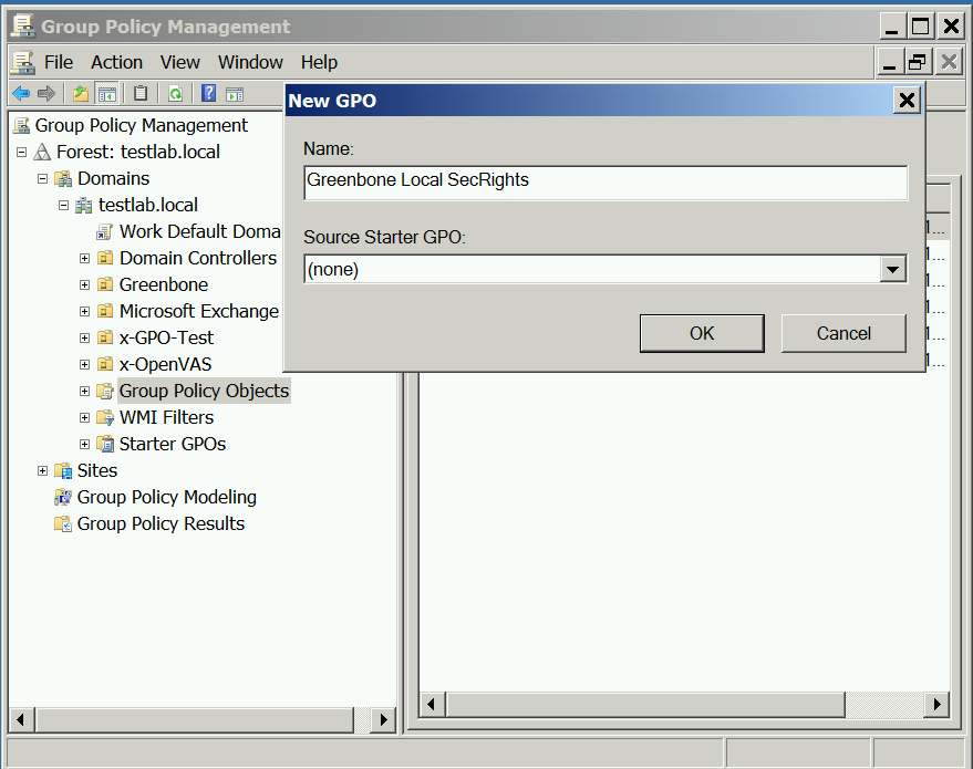
Fig. 10.9 Creating a new Microsoft Windows group policy object for Greenbone Networks scans
Click OK.
Configuring the Policy
Click the policy Greenbone Local SecRights and select Edit.
Select Computer Configuration > Policies > Windows Settings > Security Settings in the left panel.
Click Restricted Groups and select Add Group.
Click Browse… and enter
Greenbone Local Scanin the input box (see Fig. 10.10).Click Check Names.
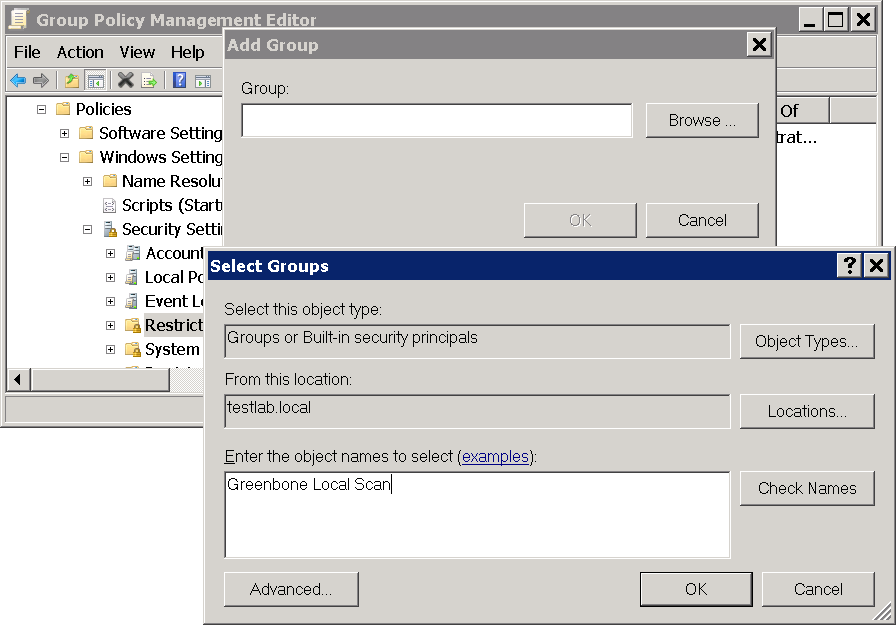
Fig. 10.10 Checking Microsoft Windows group names
Click OK twice to close the open windows.
At This group is member of click Add.
Enter
Administratorsin the input box Group (see Fig. 10.11) and click OK twice to close the open windows.Note
On non-English systems enter the respective name of the local administrator group.
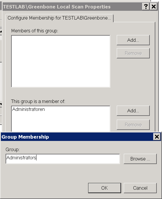
Fig. 10.11 Adding a group membership
Configuring the Policy to Deny the Group Greenbone Local Scan Logging into the System Locally
Click the policy Greenbone Local SecRights and select Edit.
Select Computer Configuration > Policies > Windows Settings > Security Settings > Local Policies > User Rights Assignment in the left panel.
In the right panel double click Deny log on locally.
Activate the checkbox Define these policy settings and click Add User or Group.
Click Browse… and enter
Greenbone Local Scanin the input box (see Fig. 10.12).Click Check Names.

Fig. 10.12 Editing the policy
Click OK three times to close the open windows.
Configuring the Policy to Deny the Group Greenbone Local Scan Logging into the System Remotely
Click the policy Greenbone Local SecRights and select Edit.
Select Computer Configuration > Policies > Windows Settings > Security Settings > Local Policies > User Rights Assignment in the left panel.
In the right panel double click Deny log on through Remote Desktop Services.
Activate the checkbox Define these policy settings and click Add User or Group.
Click Browse… and enter
Greenbone Local Scanin the input box (see Fig. 10.13).Click Check Names.
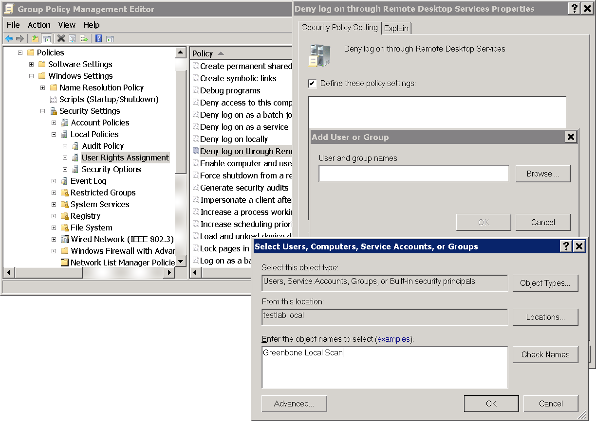
Fig. 10.13 Editing the policy
Click OK three times to close the open windows.
Configuring the Policy to Give Read Permissions Only to the Registry for the Group Greenbone Local Scan
Important
This setting still exists after the GPO has been removed (“tattooing GPO”).
This changes fundamental privileges which may not be simply reversed by removing the GPO.
Research whether the settings are compatible with the environment.
Note
The following steps are optional.
In the left panel right click Registry and select Add Key.
Select USERS and click OK (see Fig. 10.14).
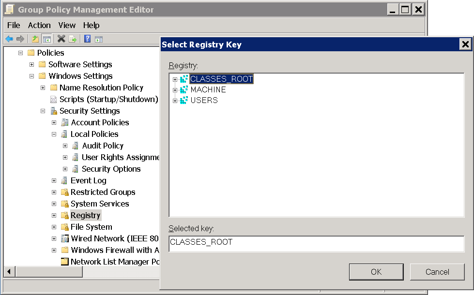
Fig. 10.14 Selecting the registry key
Click Advanced and Add.
Enter
Greenbone Local Scanin the input box and click OK (see Fig. 10.15).
Fig. 10.15 Selecting the group Greenbone Local Scan
Select This object and child objects in the drop-down-list Apply to.
Deactivate all checkboxes for Allow and activate the checkboxes Set Value, Create Subkey, Create Link, Delete, Change Permissions and Take Ownership for Deny (see Fig. 10.16).
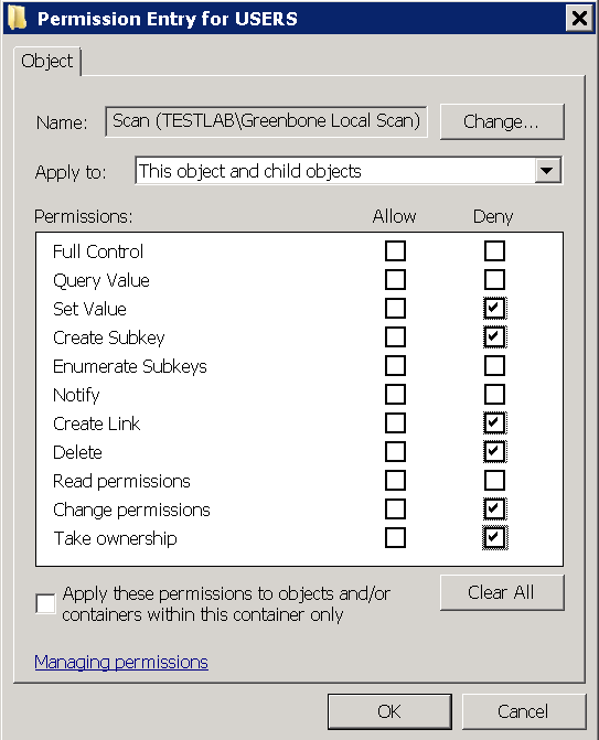
Fig. 10.16 Disallowing edition of the registry
Click OK twice and confirm the warning message by clicking Yes.
Click OK.
Select the radiobuttons Configure this key then and Propagate inheritable permissions to all subkeys and click OK (see Fig. 10.17).
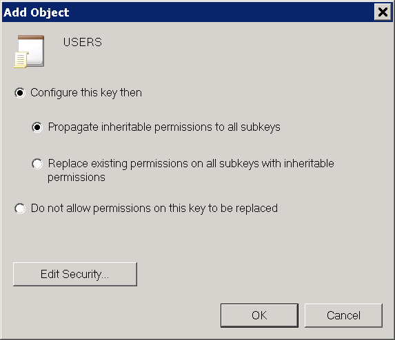
Fig. 10.17 Making the permissions recursive
Repeat the steps 2 to 9 for MACHINE and CLASSES_ROOT.
Linking the Group Policy Object
In the right panel right click the domain and select Link an Existing GPO….
Select Greenbone Local SecRights in the section Group Policy objects and click OK (see Fig. 10.18).
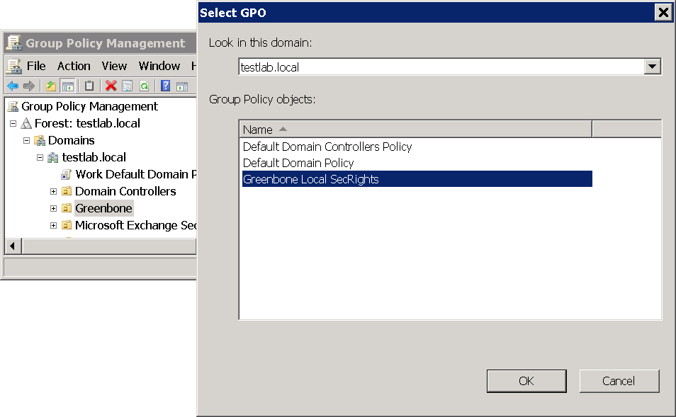
Fig. 10.18 Linking the policy
10.3.3.3. Restrictions
Based on the fact that write permissions to the registry and system drive have been removed, the following two tests will no longer work:
Leave information on scanned Windows hostsOID 1.3.6.1.4.1.25623.1.0.96171This test, if desired, creates information about the start and end of a scan under HKLM\Software\VulScanInfo. Due to denying write access to HKLM this is no longer possible. If the test should be possible, the GPO must be adjusted respectively.
Windows file ChecksumsOID 1.3.6.1.4.1.25623.1.0.96180This test, if desired, saves the tool ReHash under C:\Windows\system32 (for 32-bit systems) or C:\Windows\SysWOW64 (for 64-bit systems). Due to denying write access this is no longer possible. If the test should be possible, the tool must be saved separately or the GPO must be adjusted respectively.
More information can be found in Chapter 14.1.3.
10.3.3.4. Scanning Without Domain Administrator and Local Administrator Permissions
It is possible to build a GPO in which the user also does not have any local administrator permissions. But the effort to add respective read permissions to each registry branch and folder is huge. Unfortunately, inheriting of permissions is deactivated for many folders and branches. Additionally, these changes can be set by GPO but cannot be removed again (tattooing GPO). Specific permissions could be overwritten so that additional problems could occur as well.
Building a GPO in which the user does not have any local administrator permissions does not make sense from a technical and administrative point of view.
10.3.4. Requirements on Target Systems with Linux/Unix
For authenticated scans on Linux or Unix systems regular user access is usually enough. The login is performed via SSH. The authentication is done either with passwords or a private SSH key stored on the GSM.
Generated installation package for credentials: The install package for Linux Debian or Linux RedHat is a DEB or a RPM file creating a new user without any specific permissions. A public SSH key that is created on the GSM is stored in the user’s home folder. For users of other Linux distributions or Unix derivatives the public key is offered for download. Creating a user and saving the public key with the proper file permissions is the responsibility of the user.
In both cases it needs to be made sure that public key authentication is not prohibited by the SSH daemon. The line
PubkeyAuthentication nomust not be present.Credentials that are downloaded as a DEB file can be installed using the command
dpkg --install credential_file_name.deb.Existing SSH key pairs may also be used. SSH key pairs can be generated using the command
ssh-keygenon Linux orputtygen.exeif using PuTTY on Microsoft Windows. To use an existing SSH key pair for authentication, the private key must be supplied when the credential is created. The private SSH key must be in PEM format. The key types Ed25519, ECDSA, RSA and DSA are supported.For scans that include policy testing, root permission or the membership in specific groups (often
wheel) may be necessary. For security reasons many configuration files are only readable by super users or members of specific groups.The more permissions a user has, the more results and settings can be detected on a system. In some cases root user access may be required.
The following commands are executed with root user access during an authenticated scan.
Important
- This list is not static. New or changed VTs may add new commands at any time.
- Depending on the found software, additional commands may be executed.
- The executed commands depend on the Linux distribution and the selected scan configuration.
- bash
- cat
- date
- dpkg
- egrep
- find
- grep
- host
- id
- ifconfig
- lastlog
- locate
- ls
- md5sum
- mlocate
- netstat
- perl
- ps
- rpm
- sh
- sha1sum
- slocate
- uname
- uptime
- whereis
- which
The installation of the package
locate(alternativelymlocate) to provide the commandlocate/mlocateon the target system is recommended. The use of this command reduces calls to the commandfindused to search for files and thus, improves the search performance and lowers the resource usage on the target system.For the commands to work, the corresponding database permissions and regular database updates, e.g., via a cron job, may need to be configured.
10.3.5. Requirements on Target Systems with ESXi
By default, local ESXi users are limited to read-only roles. Either an administrative account or a read-only role with permission to global settings has to be used. This can be set up as follows:
Start the Vsphere client.
Select Administration > Roles in the menu bar (see Fig. 10.19).
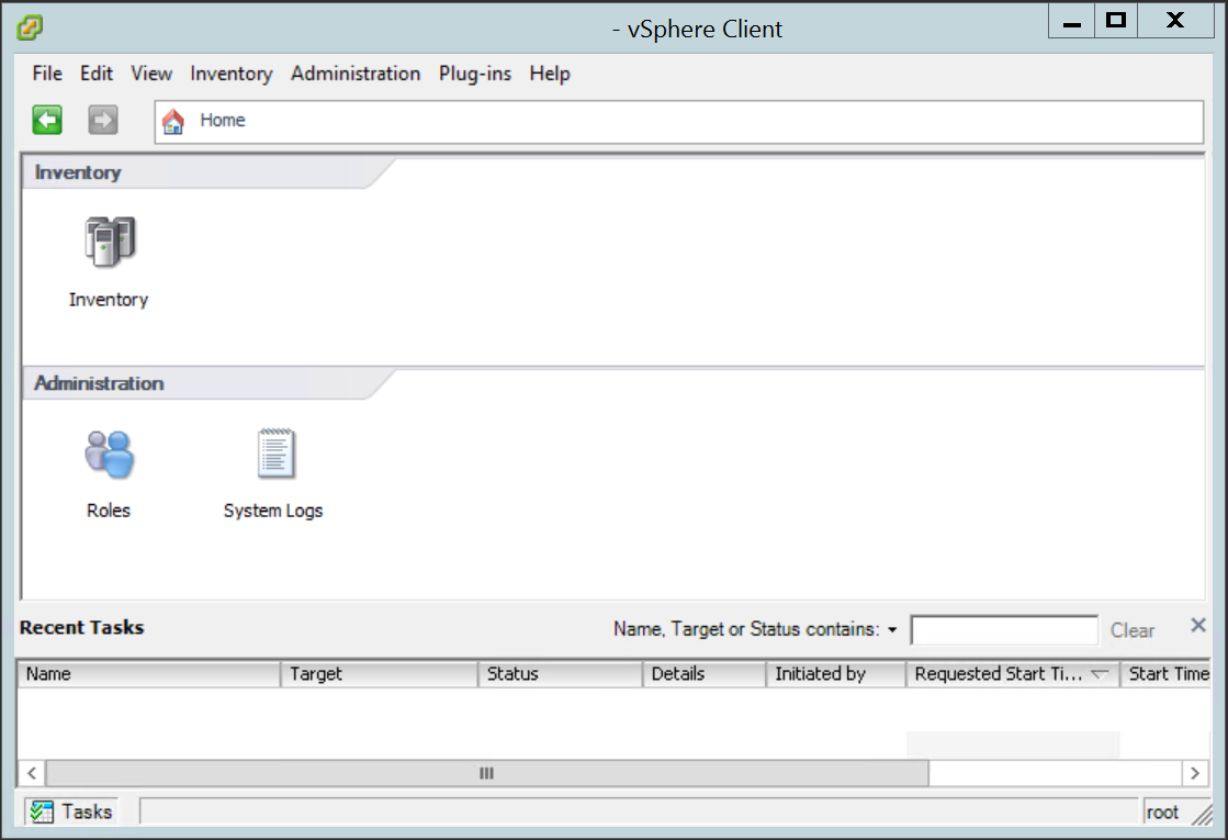
Fig. 10.19 Vsphere client offering access to the roles
→ The roles are displayed.
Right click ReadOnly and select Clone (see Fig. 10.20).
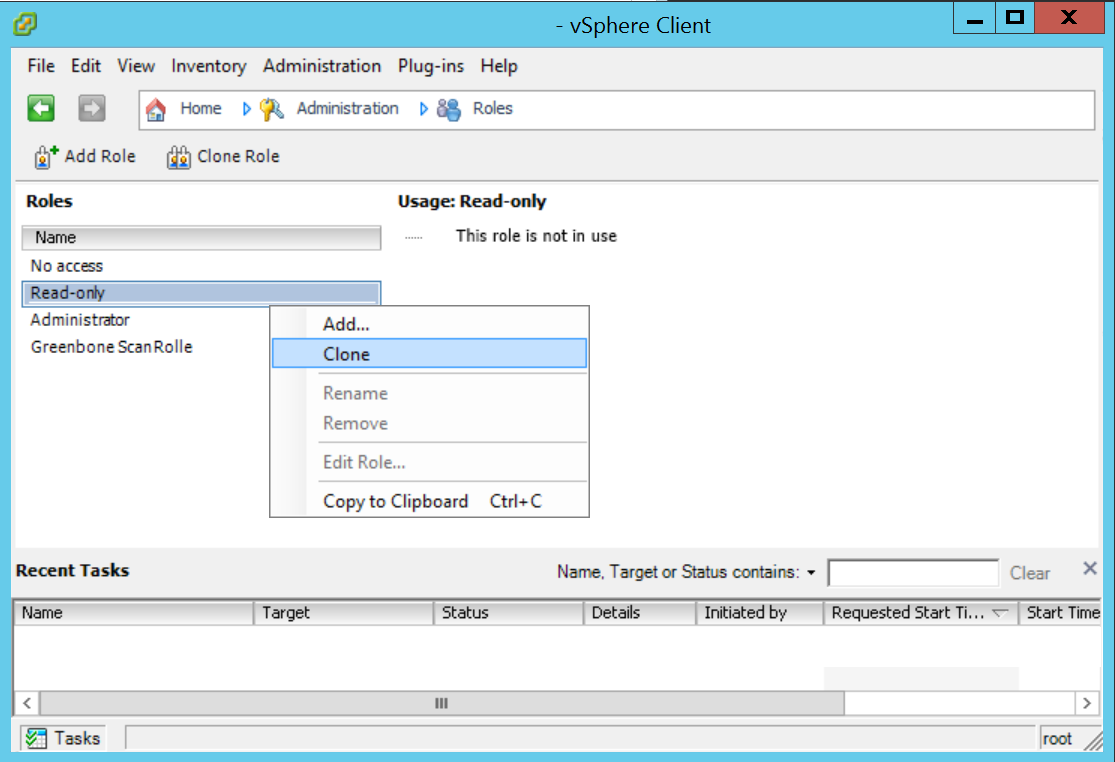
Fig. 10.20 Displaying the roles
→ The cloned role is displayed as well.
Right click the cloned role and select Rename.
Enter the new name of the cloned role in the input box and click OK.
Right click the cloned role and select Edit Role….
Unfold Global and activate the checkbox Settings (see Fig. 10.21).
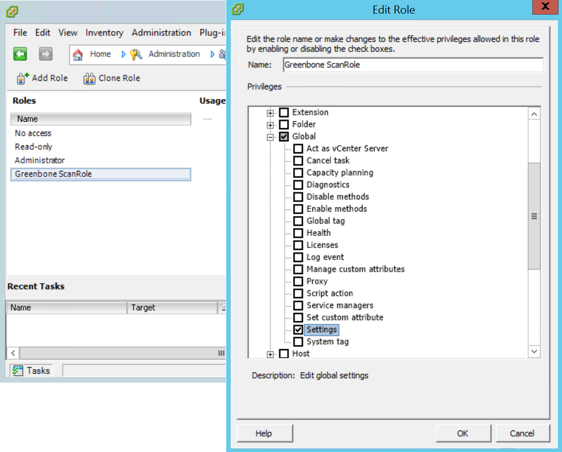
Fig. 10.21 Editing the role
Click OK.
Select Inventory > Inventory in the menu bar.
Open the tab Permissions.
Right click in the empty space and select Add Permission… (see Fig. 10.22).
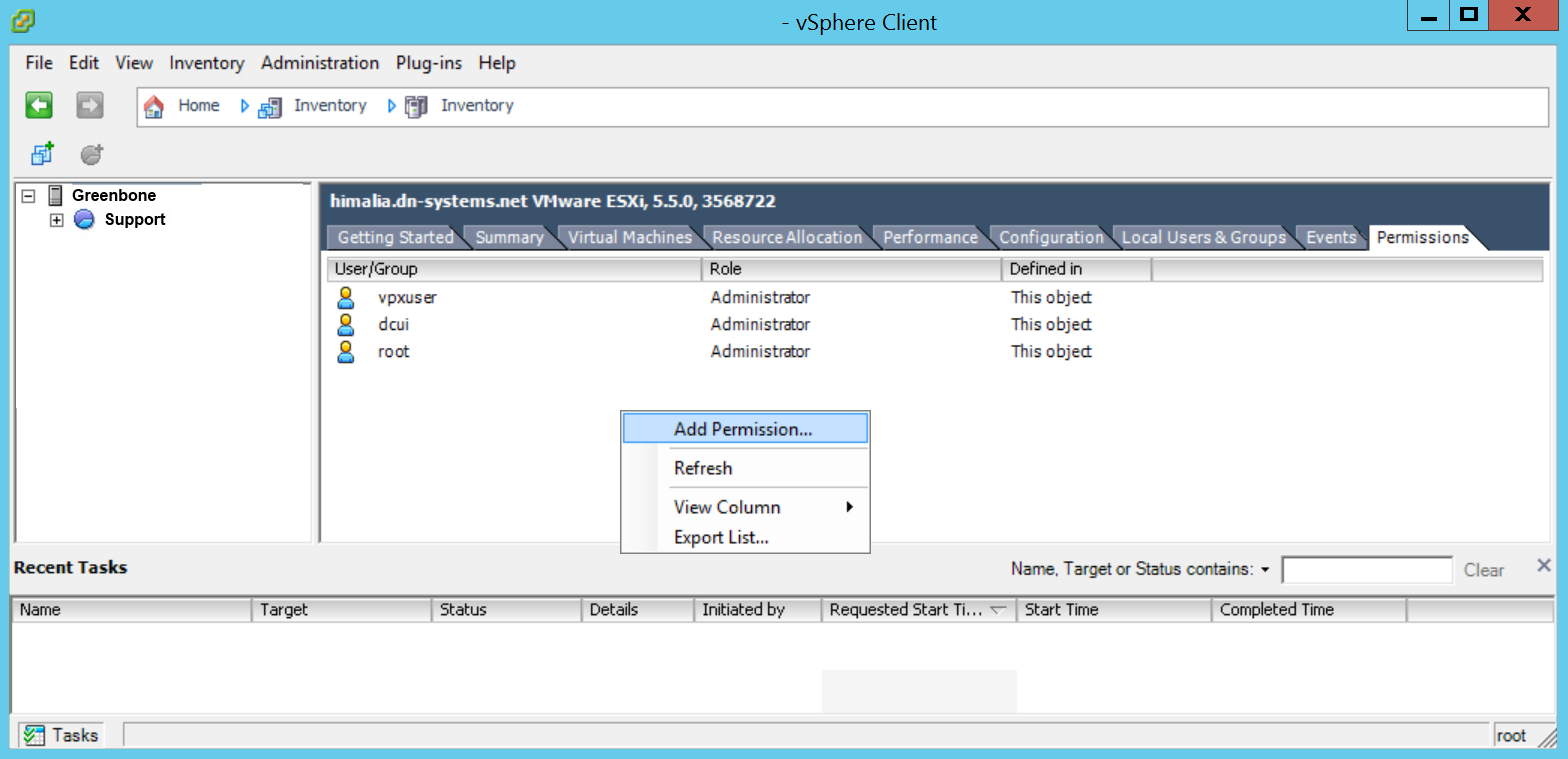
Fig. 10.22 Adding a permission to the scan user
Select the scan user account used by the GSM in the left section (see Fig. 10.23).
Select the created role in the drop-down-list in the right section (see Fig. 10.23).
Click OK.
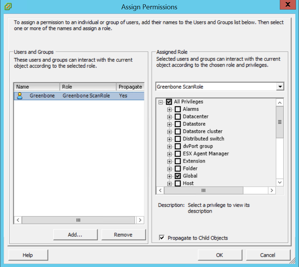
Fig. 10.23 Assigning the role to the scan user
10.3.6. Requirements on Target Systems with Cisco OS
The GSM can check network components like routers and switches for vulnerabilities as well. While the usual network services are discovered and checked via the network some vulnerabilities can only be discovered by an authenticated scan. For the authenticated scan the GSM can use either SNMP or SSH.
10.3.6.1. SNMP
The GSM can use the SNMP protocol to access the Cisco network component. The GSM supports SNMPv1, v2c and v3. SNMP uses the port 161/udp. The default port list does not include any UDP port. Therefore, this port is ignored during the vulnerability test using Full and fast and no SNMP check is enabled. To scan network components the port list should be modified to include at least the following ports:
- 22/tcp SSH
- 80/tcp 8080/tcp HTTP
- 443/tcp 8443/tcp HTTPS
- 2000/tcp SCCP
- 2443/tcp SCCPS
- 5060/tcp 5060/udp SIP
- 5061/tcp 5061/udp SIPS
- 67/udp DHCP Server
- 69/udp TFTP
- 123/udp NTP
- 161/udp SNMP
- 162/udp SNMP Traps
- 500/udp IKE
- 514/udp Syslog
- 546/udp DHCPv6
- 6161/udp 6162/udp Unified CM
The administrator can set up special port lists used only for such network components.
The GSM needs to access only very few objects from the SNMP tree. For a less privileged access an SNMP view should be used to constrain the visibility of the SNMP tree for the GSM. The following two examples explain how to set up the view using either a community string or an SNMPv3 user.
To use an SNMP community string the following commands are required on the target:
# configure terminal
Using an access list the usage of the community can be restricted. The IP address of the GSM is 192.168.222.74 in this example:
(config) # access-list 99 permit 192.168.222.74
The view gsm should only allow accessing the system description:
(config) # snmp-server view gsm system included
(config) # snmp-server view gsm system.9 excluded
The last command links the community gsm-community with the view gsm and the access list 99:
(config) # snmp-server community gsm-community view gsm RO 99
If using an SNMPv3 user including encryption the following configuration lines are required on the target:
# configure terminal
(config) # access-list 99 permit 192.168.222.74
(config) # snmp-server view gsm system included
(config) # snmp-server view gsm system.9 excluded
SNMPv3 requires the setup of a group first. Here the group gsmgroup is linked to the view gsm and the access list 99:
(config) # snmp-server group gsmgroup v3 priv read gsm access 99
Now the user can be created supplying the password gsm-password and the encryption key gsm-encrypt. The authentication is done using MD5 while the encryption is handled by AES128:
(config) # snmp-server user gsm-user gsm-group v3 auth md5 gsm-password priv
aes 128 gsm-encrypt
To configure either the community or the SNMPv3 user in the GSM the administrator selects Configuration > Credentials in the menu bar (see Chapter 10.3.2).
10.3.6.2. SSH
The authenticated scan can be performed via SSH as well.
If using SSH, the usage of a special unprivileged user is recommended.
The GSM currently requires only the command show version to retrieve the current version of the firmware of the device.
To set up a less privileged user which is only able to run this command, several approaches are possible. The following example uses the role based access control feature.
Tip
Before using the following example, make sure all side effects of the configuration are understood. If used without verification the system may restrict further logins via SSH or console.
To use role based access control AAA and views have to be enabled:
> enable
# configure terminal
(config)# aaa new-model
(config)# exit
> enable view
# configure terminal
The following commands create a restricted view including just the command show version. The supplied password view-pw is not critical:
(config)# parser view gsm-view
(config-view)# secret 0 view-pw
(config-view)# commands exec include show version
(config-view)# exit
Now the user gsm-user with the password gsm-pw is created and linked to the view gsm-view:
(config)# username gsm-user view gsm-view password 0 gsm-pw
(config)# aaa authorization console
(config)# aaa authorization exec default local
If SSH is not enabled yet the following commands take care of that. Use the appropriate host name and domain:
(config)# hostname switch
(config)# ip domain-name greenbone.net
(config)# crypto key generate rsa general-keys modulus 2048
Finally, enable SSH logins using the following commands:
(config)# line vty 0 4
(config-line)# transport input ssh
(config-line)# Crtl-Z
The credentials of the user need to be entered on the GSM. Select Configuration > Credentials in the menu bar and create the appropriate user (see Chapter 10.3.2).
Link the credentials to the target to be used as SSH credentials.
10.4. Configuring a Prognosis Scan
Not every vulnerability justifies a new scan of the network or of individual systems. If the GSM has already obtained information about vulnerabilities by former scans, it can make a prognosis of which security risks could exist.
Using the CVE scanner allows forecasting possible security risks based on current information about known security risks from the SecInfo management (see Chapter 13) without the need of a new scan. This is especially interesting for environments in which most vulnerabilities have been removed or remediated by using the GSM.
If security risks become known, an actual scan can be run to verify the prognosis.
Note
The asset database requires current data for the CVE scanner. A full scan, e.g. with the scan configuration Full and fast, has to be performed and the results have to be added to the assets.
The results of a prognosis scan rely on the availability of self-reported versions from exposed software found during a full scan. Using an authenticated scan may increase the results found by the prognosis scan.
A full scan of the systems should occur regularly in weekly or monthly intervals.
A prognosis scan can be run as follows:
Run a full scan (see Chapter 10.2).
Note
A full scan configuration has to be chosen, e.g. Full and fast.
Additionally, the radiobutton Yes has to be selected for Add results to Assets.
Select Scans > Tasks in the menu bar.
Create a new task by moving the mouse over
and clicking New Task.Define the task (see Chapter 10.2.2).
Select CVE in the drop-down-list Scanner.
Click Save.
In the row of the task click
.→ The scan is running. For the status of a task see Chapter 10.8.
Tip
The report of a task can be displayed as soon as the task has been started by clicking the bar in the column Status. For reading, managing and downloading reports see Chapter 11.
As soon as the status changes to Done the complete report is available. At any the time the intermediate results can be reviewed (see Chapter 11.2.1).
Note
It can take a while for the scan to complete. The page is refreshing automatically if new data is available.
When the scan is completed select Scans > Reports in the menu bar.
Click on the date of the report to show the results.
→ The report shows each found CVE as a vulnerability (see Fig. 10.24).
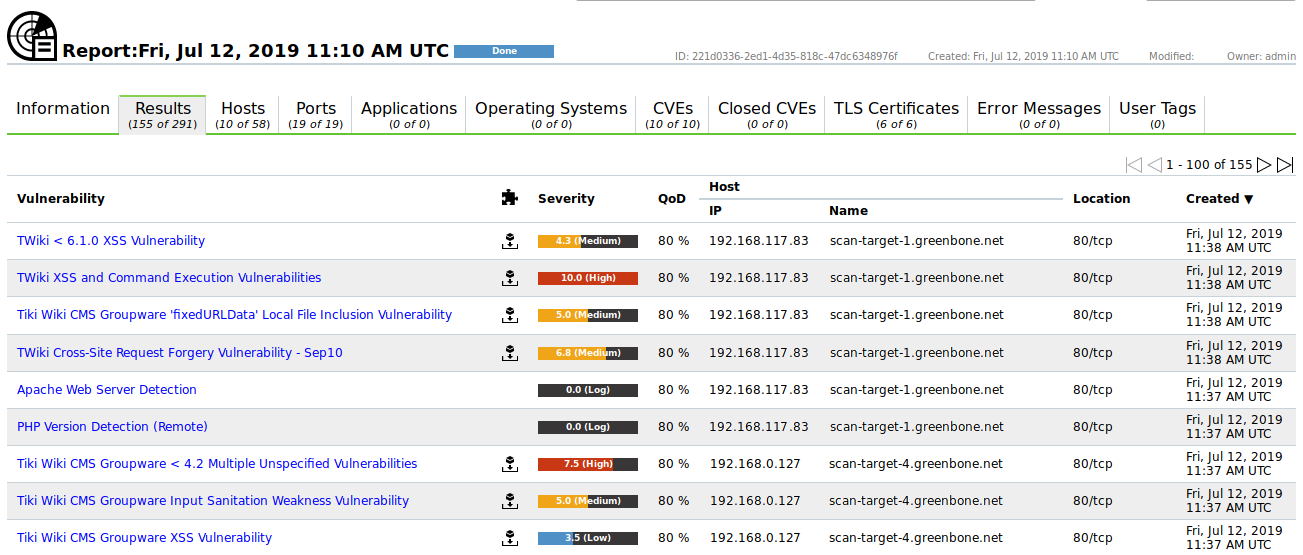
Fig. 10.24 Results of a prognosis scan
Click on a vulnerability and click
.→ The details page of the vulnerability is opened.
The NVT to which the result is assigned is displayed in the section Detection Method (see Fig. 10.25). By clicking on the NVT the details page of the corresponding NVT is opened.
Tip
For available actions on this page see Chapter 11.2.1.
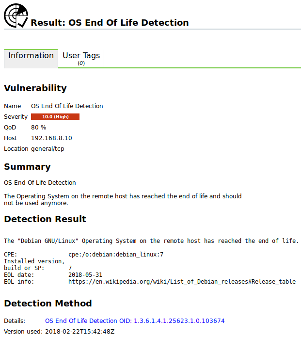
Fig. 10.25 Details of a detected CVE
Note
The CVE scanner might show false positives as it does not check whether the vulnerability actually exists.
10.5. Creating a Container Task
A container task can be used to import and provide reports created on other GSMs.
A container task can be created as follows:
Select Scans > Tasks in the menu bar.
Create a new container task by moving the mouse over
and clicking New Container Task.Enter the name of the container task in the input box Name (see Fig. 10.26).
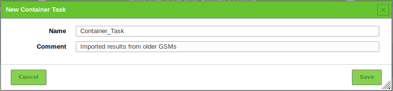
Fig. 10.26 Creating a container task
Click Save.
To add a report to the container task click
 in the row of the container task.
Click Browse… and select the XML file of a report (see Fig. 10.27).
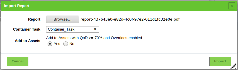
Fig. 10.27 Adding a report to a container task
Select the radiobutton Yes to add the report to the assets (see Chapter 12).
Click Import.
List Page
All existing container tasks can be displayed by selecting Scans > Tasks in the menu bar.
Note
Container tasks can be identified by  in the column Status.
For all container tasks the following actions are available:
- Import reports to the container task.
- Delete the container task.
- Edit the container task.
- Clone the container task.
- Export the container task as an XML object.
Note
By clicking or below the list of tasks more than one task can be deleted or exported at a time. The drop-down-list is used to select which tasks are deleted or exported.
Details Page
Click on the name of a container task to display the details of the container task. Click to open the details page of the container task.
The following registers are available:
- Information
- General information about the container task.
- User Tags
- Assigned tags (see Chapter 8.5).
- Permissions
- Assigned permissions (see Chapter 9.4).
The following actions are available in the upper left corner:
- Open the corresponding chapter of the user manual.
- Show the list page of all container tasks.
- Create a new task (see Chapter 10.2.2) or container task (see Chapter 10.5).
- Clone the container task.
- Edit the container task.
- Delete the container task.
- Export the container task as an XML object.
- Import reports to the container task.
 Show the last report for the container task or show all reports for the container task.
 Show the results for the container task.
 Show the notes for the container task.
 Show the overrides for the container task.
10.6. Managing Targets
List Page
All existing targets can be displayed by selecting Configuration > Targets in the menu bar.
For all targets the following information is displayed:
- Name
- Name of the target.
- Hosts
- Hosts that are scanned if the target is used for a scan (see Chapter 10.2.2).
- IPs
- Number of scanned hosts.
- Port List
- Port list used if the target is used for a scan (see Chapter 10.2.2).
- Credentials
- Credentials configured for the target.
For all targets the following actions are available:
- Delete the target. Only targets which are currently not used can be deleted.
- Edit the target.
- Clone the target.
- Export the target as an XML file.
Note
By clicking or below the list of targets more than one target can be deleted or exported at a time. The drop-down-list is used to select which targets are deleted or exported.
Details Page
Click on the name of a target to display the details of the target. Click to open the details page of the target.
The following registers are available:
- Information
- General information about the target.
- User Tags
- Assigned tags (see Chapter 8.5).
- Permissions
- Assigned permissions (see Chapter 9.4).
The following actions are available in the upper left corner:
- Open the corresponding chapter of the user manual.
- Show the list page of all targets.
- Create a new target (see Chapter 10.2.1).
- Clone the target.
- Edit the target.
- Delete the target. Only targets which are currently not used can be deleted.
- Export the target as an XML file.
10.7. Creating and Managing Port Lists
If applications run on unusual ports and they should be monitored and tested with the GSM, the default port lists should be adapted. If necessary, an individual port list including the desired port can be created.
10.7.1. Creating a Port List
A new port list can be created as follows:
Select Configuration > Port Lists in the menu bar.
Create a new port list by clicking
.Define the port list (see Fig. 10.28).
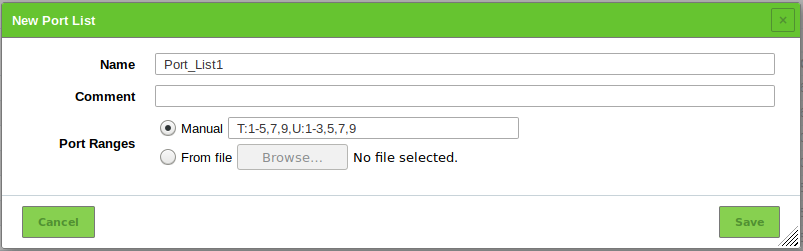
Fig. 10.28 Creating a new port list
Click Save.
The following details of the port list can be defined:
- Name
- Definition of the name. The name can be chosen freely.
- Comment
- An optional comment can contain additional information.
- Port Ranges
Manual entry of the port ranges or importing of a list of the port ranges. If entering manually, the port ranges are separated by commas. If importing from a file, the entries can be separated with commas or line breaks. The file should use UTF-8 text encoding.
Each value in the list can be a single port (e.g.
7) or a port range (e.g.9-11). These options can be mixed (e.g.5, 7, 9-11, 13).An entry in the list can be preceded by a protocol specifier (
T:for TCP,U:for UDP), e.g.T:1-3, U:7, 9-11(TCP ports 1, 2 and 3, UDP ports 7, 9, 10 and 11). If no specifier is given, TCP is assumed.
10.7.2. Managing Port Lists
List Page
All existing port lists can be displayed by selecting Configuration > Port Lists in the menu bar.
For all port lists the following information is displayed:
- Name
- Name of the port list. A global port list is marked with
 .
. - Total
- Total number of ports in the port list.
- TCP
- Number of TCP ports in the port list.
- UDP
- Number of UDP ports in the port list.
For all port lists the following actions are available:
- Delete the port list. Only port lists which are currently not used can be deleted.
- Edit the port list. Only port lists which are currently not used can be edited.
- Clone the port list.
- Export the port list as an XML file.
Note
By clicking or below the list of port lists more than one port list can be deleted or exported at a time. The drop-down-list is used to select which port lists are deleted or exported.
Details Page
Click on the name of a port list to display the details of the port list. Click to open the details page of the port list.
The following registers are available:
- Information
- General information about the port list.
- Port Ranges
- All port ranges included in this port list. The first and the last port of a range as well as the protocol specifier are displayed.
- User Tags
- Assigned tags (see Chapter 8.5).
- Permissions
- Assigned permissions (see Chapter 9.4).
The following actions are available in the upper left corner:
- Open the corresponding chapter of the user manual.
- Show the list page of all port lists.
- Create a new port list (see Chapter 10.7.1).
- Clone the port list.
- Edit the port list. Only port lists which are currently not used can be edited.
- Delete the port list. Only port lists which are currently not used can be deleted.
- Export the port list as an XML file.
10.8. Managing Tasks
List Page
All existing tasks can be displayed by selecting Scans > Tasks in the menu bar.
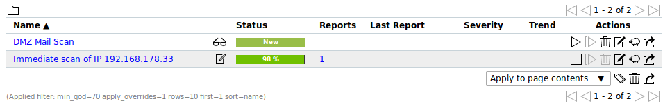
Fig. 10.29 Page Tasks displaying all tasks
For all tasks the following information is displayed:
- Name
Name of the task. The following icons may be displayed:
 The task is marked as alterable. Some properties that would otherwise be locked once reports exist can be edited.
 The task is configured to run on a remote scanner (see Chapter 16).
 The task is visible to one or more other user(s). The task is owned by another user.
- Status
Current status of the task. The following status bars are possible:
 The task has not been run since it was created.
 The task was just started.
The GSM is preparing the scan.
The task was just started.
The GSM is preparing the scan. The task is currently running.
The percent value is based on the number of NVTs executed on the selected hosts.
For this reason the value does not necessarily correlate with the time spent.
The task is currently running.
The percent value is based on the number of NVTs executed on the selected hosts.
For this reason the value does not necessarily correlate with the time spent. The task was deleted.
The actual deletion process can take some time as reports need to be deleted as well.
The task was deleted.
The actual deletion process can take some time as reports need to be deleted as well. The task was requested to stop recently.
However, the scan engine has not yet reacted to this request yet.
The task was requested to stop recently.
However, the scan engine has not yet reacted to this request yet. The task was stopped.
The latest report is possibly not yet complete.
Other reasons for this status could be the reboot of the GSM or a power outage.
After restarting the scanner, the task will be resumed automatically.
The task was stopped.
The latest report is possibly not yet complete.
Other reasons for this status could be the reboot of the GSM or a power outage.
After restarting the scanner, the task will be resumed automatically. The task was just resumed.
The GSM is preparing the scan.
The task was just resumed.
The GSM is preparing the scan.When resuming a scan, all unfinished hosts are scanned completely anew. The data of hosts that were already fully scanned is kept.
 An error has occurred and the task was interrupted.
The latest report is possibly not complete yet or is missing completely.
An error has occurred and the task was interrupted.
The latest report is possibly not complete yet or is missing completely. The task has been completed successfully. The task is a container task.
 The report is currently being uploaded into the container task.
- Reports
- Number of reports for the task. By clicking on the number of reports the page Reports is opened. A filter is applied to show only the reports for the selected task.
- Last Report
- Date and time of the latest report. By clicking it the details page of the latest report is opened.
- Severity
- Highest severity found by a scan of the task.
- Trend
- Change of vulnerabilities between the newest and the second newest report (see Chapter 11.5).
For all tasks the following actions are available:
- Start the task. Only currently not running tasks can be started.
 Stop the currently running task. All discovered results will be written to the database.
- Show details of the assigned schedule (only available for scheduled tasks, see Chapter 10.10).
 Resume the stopped task. All unfinished hosts are scanned completely anew. The data of hosts that were already fully scanned is kept.
- Delete the task.
- Edit the task.
- Clone the task.
- Export the task as an XML object.
Note
By clicking or below the list of tasks more than one task can be deleted or exported at a time. The drop-down-list is used to select which tasks are deleted or exported.
Details Page
Click on the name of a task to display the details of the task. Click to open the details page of the task.
The following registers are available:
- Information
- General information about the task.
- User Tags
- Assigned tags (see Chapter 8.5).
- Permissions
- Assigned permissions (see Chapter 9.4).
The following actions are available in the upper left corner:
- Open the corresponding chapter of the user manual.
- Show the list page of all tasks.
- Create a new task (see Chapter 10.2.2) or container task (see Chapter 10.5).
- Clone the task.
- Edit the task.
- Delete the task.
- Export the task as an XML object.
- Start the task. Only currently not running tasks can be started.
- Stop the currently running task. All discovered results will be written to the database.
- Resume the stopped task. All unfinished hosts are scanned completely anew. The data of hosts that were already fully scanned is kept.
- Show the last report for the task or show all reports for the task.
- Show the results for the task.
- Show the notes for the task.
- Show the overrides for the task.
10.8.1. Granting Permissions for a Task
On the details page of a task permissions for the task can be managed as follows:
Note
By default, regular users cannot create permissions for other users as they do not have access to the user database. To be able to create permissions for other users, a user must have the global and the specific get_users permission (see Chapter 9.4.3).
- Select Scans > Tasks in the menu bar.
- Click on the name of a task to display the details of the task. Click to open the details page of the task.
- Click on the register Permissions.
- In the section Permissions click .
- Select the permission type in the drop-down-list Grant.
- Select the radiobutton User, Group or Role and select the user/role/group in the respective drop-down-list (see Fig. 10.30).
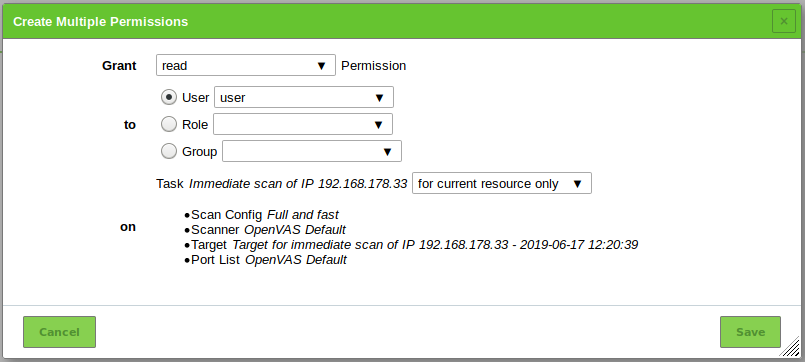
Fig. 10.30 Creating a new permission
Click Save.
→ The permission is displayed on the details page of the task (see Fig. 10.31).
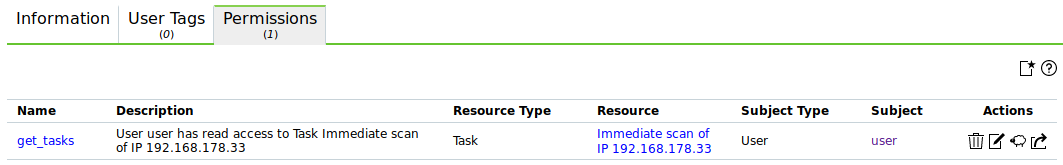
Fig. 10.31 Permission displayed on the details page of a task
After logging in the user can see the task and can access the respective reports.
10.9. Configuring and Managing Scan Configurations
The GSM appliance comes with various predefined scan configurations. They can be customized and new scan configurations can be created.
10.9.1. Default Scan Configurations
The following configurations are already available:
- Empty
- This is an empty template.
- Discovery
- Only NVTs that provide information of the target system are used. No vulnerabilities are being detected.
- Host Discovery
- Only NVTs that discover target systems are used. This scan only reports the list of systems discovered.
- System Discovery
- Only NVTs that discover target systems including installed operating systems and hardware in use are used.
- Full and fast
For many environments this is the best option to start with.
This scan configuration is based on the information gathered in the previous port scan and uses almost all NVTs. Only NVTs that will not damage the target system are used. NVTs are optimized in the best possible way to keep the potential false negative rate especially low. The other configurations only provide more value in rare cases but with much higher effort.
- Full and fast ultimate
- This scan configuration expands the scan configuration Full and fast with NVTs that could disrupt services or systems or even cause shutdowns.
- Full and very deep
- This scan configuration is based on the scan configuration Full and fast but the results of the port scan or the application/service detection do not have an impact on the selection of the NVTs. Therefore, NVTs that wait for a timeout or test for vulnerabilities of an application/service which were not detected previously are used. A scan with this scan configuration is very slow.
- Full and very deep ultimate
- This scan configuration expands the scan configuration Full and very deep with dangerous NVTs that could cause possible service or system disruptions. A scan with this scan configuration is very slow.
10.9.2. Managing Scan Configurations
All existing scan configurations can be displayed by selecting Configuration > Scan Configs in the menu bar.
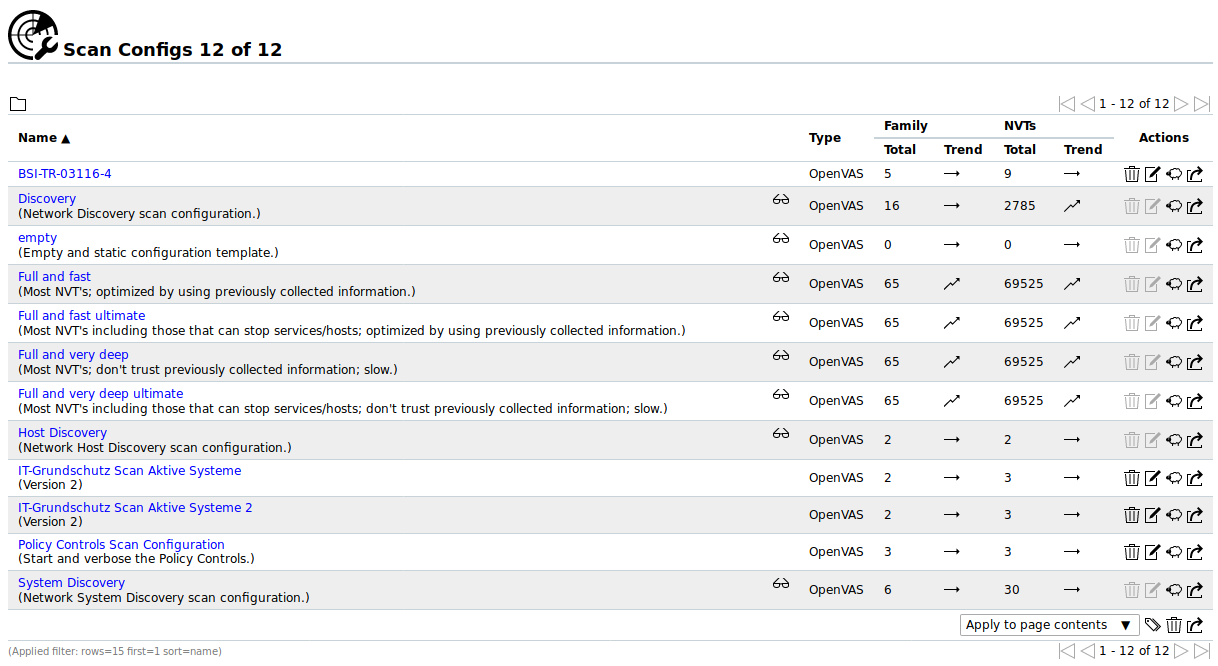
Fig. 10.32 Page Scan Configs displaying all available scan configurations
For all scan configurations the following information is displayed:
- Name
- Name of the scan configuration. A global scan configuration is marked with .
- Type
- Type of the scan configuration.
- Family – Total
- Number of activated NVT families for the scan configuration.
- Family – Trend
Trend of NVT families
 New NVT families are included and activated automatically after an NVT feed update. This ensures that new NVTs are available immediately and without any interaction by the administrator.
 New NVT families are not included automatically after an NVT feed update.
- NVTs – Total
- Number of activated NVTs for the scan configuration.
- NVTs – Trend
Trend of NVTs.
New NVTs of the activated NVT families are included and activated automatically after an NVT feed update. This ensures that new NVTs are available immediately and without any interaction by the administrator. New NVTs are not included automatically after an NVT feed update.
Note
Greenbone Networks publishes new NVTs regularly. New families of NVTs can be introduced through the Greenbone Security Feed as well.
For all scan configurations the following actions are available:
- Delete the scan configuration. Only self-created scan configurations which are currently not used can be deleted.
- Edit the scan configuration. Only self-created scan configurations which are currently not used can be edited.
- Clone the scan configuration.
- Export the scan configuration as an XML file.
Note
By clicking or below the list of scan configurations more than one scan configuration can be deleted or exported at a time.
The drop-down-list is used to select which scan configurations are deleted or exported.
Click on the name of a scan configuration to display the details of the scan configuration. Click to open the details page of the scan configuration.
The following registers are available:
- Scanner Preferences
- All scanner preferences for the scan configuration with current and default values (see Chapter 10.9.5.1).
- NVT Families
- All NVT families for the scan configuration with the number of activated NVTs and the trend.
- NVT Preferences
- All NVT preferences for the scan configuration (see Chapter 10.9.6.1).
- User Tags
- Assigned tags (see Chapter 8.5).
- Permissions
- Assigned permissions (see Chapter 9.4).
The following actions are available in the upper left corner:
- Open the corresponding chapter of the user manual.
- Show the list page of all scan configurations.
- Create a new scan configuration (see Chapter 10.9.3).
- Clone the scan configuration.
- Edit the scan configuration. Only self-created scan configurations which are currently not used can be edited.
- Delete the scan configuration. Only self-created scan configurations which are currently not used can be deleted.
- Export the scan configuration as an XML file.
 Import a scan configuration (see Chapter 10.9.4).
10.9.3. Creating a Scan Configuration
Tip
Greenbone Networks offers different scan configurations on their website (see Chapter 14).
A new scan configuration can be created as follows:
Select Configuration > Scan Configs in the menu bar.
Create a new scan configuration by clicking
.Note
Alternatively, a scan configuration can be imported (see Chapter 10.9.4).
Enter the name of the scan configuration in the input box Name (see Fig. 10.33).
Select the radiobutton of the base that should be used.
It can be chosen between Empty, static and fast and Full and fast.
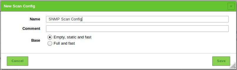
Fig. 10.33 Creating a new scan configuration
Click Save.
→ The scan configuration is created and displayed on the page Scan Configs.
In the row of the scan configuration click
.In the sections Edit Network Vulnerability Test Families select the radiobutton
if newly introduced NVT families should be included and activated automatically (see Fig. 10.34).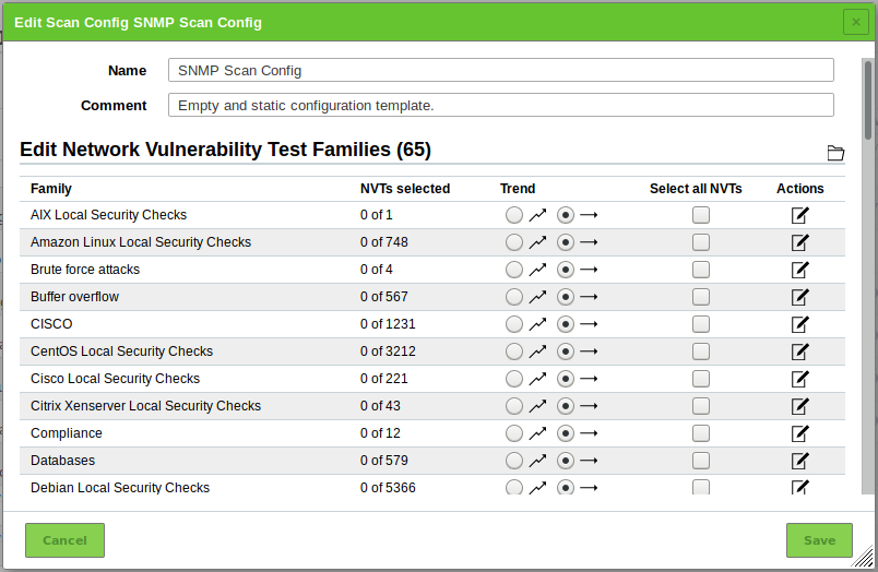
Fig. 10.34 Editing the new scan configuration
In the section Edit Network Vulnerability Test Families activate the checkboxes in the column Select all NVTs if all NVTs of a family should be activated.
Click
for an NVT family to edit it (see Fig. 10.35).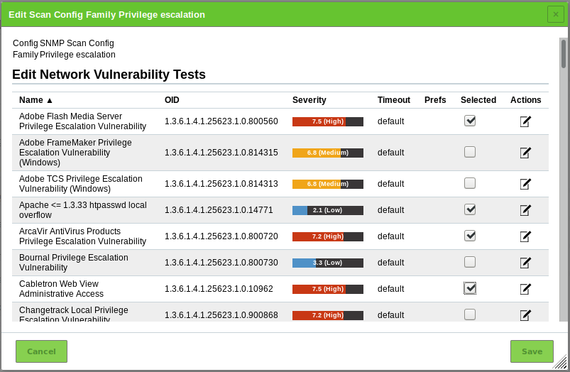
Fig. 10.35 Editing a family of NVTs
In the column Selected activate the checkboxes of the NVTs that should be activated.
Click
for an NVT to edit it (see Fig. 10.36).Note
If editing the NVT includes uploading a text file, the file should use UTF-8 text encoding.
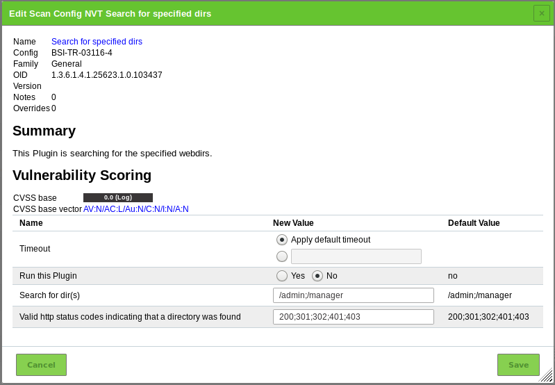
Fig. 10.36 Editing an NVT
Click Save to save the NVT.
Click Save to save the family of NVTs.
Optional: edit scanner preferences (see Chapter 10.9.5).
Optional: edit NVT preferences (see Chapter 10.9.6).
Click Save to save the scan configuration.
10.9.4. Importing a Scan Configuration
A scan configuration can be imported as follows:
Select Configuration > Scan Configs in the menu bar.
Click
.Click Browse… and select the XML file of the scan configuration.
Click Create.
Note
If the name of the imported scan configuration already exists, a numeric suffix is added to the name.
→ The imported scan configuration is displayed on the page Scan Configs.
Execute steps 6 to 16 of Chapter 10.9.3 to edit the scan configuration.
10.9.5. Editing the Scanner Preferences
Scanner preferences can be edited as follows:
Select Configuration > Scan Configs in the menu bar.
In the row of the scan configuration click
.In the section Edit Scanner Preferences click
 to edit the scanner preferences (see Fig. 10.37).
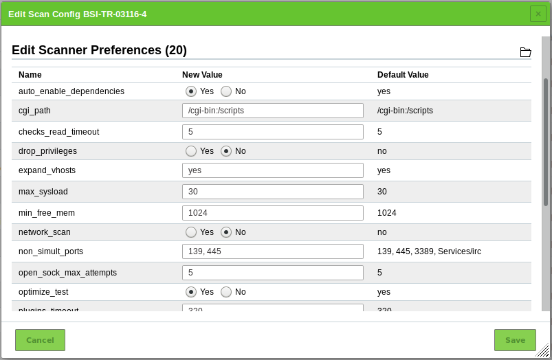
Fig. 10.37 Editing the scanner preferences
After editing the scanner preferences click Save to save the scan configuration.
10.9.5.1. Description of Scanner Preferences
Note
Documenting all scanner preferences is out of scope of this document. Only the most important preferences of the scanner are covered.
Undocumented preferences may also be deprecated despite still being visible. These preferences will be ignored by the scanner and should not be considered.
- auto_enable_dependencies: This defines whether NVTs that are required by other NVTs are activated automatically.
- cgi_path: Path used by the NVTs to access CGI scripts.
- checks_read_timeout: Timeout for the network sockets during a scan.
- drop_privileges: With this parameter the OpenVAS scanner gives up root privileges before starting the NVTs. This increases the security but results in fewer findings with some NVTs.
- test_empty_vhost: The scanner also scans the target by using empty vhost values in addition to the target’s associated vhost values.
- max_sysload: Maximum load on the GSM. Once this load is reached, no further NVTs are started until the load drops below this value again.
- min_free_mem: Minimum available memory (in MB) which should be kept free on the GSM. Once this limit is reached, no further NVTs are started until sufficient memory is available again.
- network_scan: This is an experimental option which scans the entire network all at once instead of starting Nmap for each individual host. This can save time in specific environments.
- non_simult_ports: These ports are not being tested simultaneously by NVTs.
- optimize_test: NVTs will only be started if specific prerequisites are met (e.g. open ports or detected application).
- plugins_timeout: Maximum run time of an NVT.
- safe_checks: Some NVTs can cause damage on the host system. This setting disables those respective NVTs.
- scanner_plugins_timeout: Maximum run time (in seconds) for all NVTs of the NVT family Port scanners. If an NVT runs longer, it is terminated.
- expand_vhosts: The target’s host list of vhosts is expanded with values gathered from sources such as reverse lookup queries and VT checks for SSL/TLS certificates.
- time_between_request: Wait time (in milliseconds) between two actions such as opening a TCP socket, sending a request through the open tcp socket and closing the TCP socket.
- timeout_retry: Number of retries if a socket connection attempt times out.
- unscanned_closed: This defines whether TCP ports that were not scanned should be treated like closed ports.
- unscanned_closed_udp: This defines whether UDP ports that were not scanned should be treated as closed ports.
10.9.6. Editing the NVT Preferences
- Select Configuration > Scan Configs in the menu bar.
- In the row of the scan configuration click .
- In the section Network Vulnerability Test Preferences click to edit the NVT preferences.
- In the row of the NVT preference click .
- Edit the NVT preference.
- Click Save to save the NVT preference.
- Click Save to save the scan configuration.
10.9.6.1. Description of NVT Preferences
Note
Documenting all NVT preferences is out of scope of this document. Only the NVT preferences of the Nmap and Ping Host port scanners are covered for now.
10.9.6.1.1. Preferences of the NVT Ping Host
The NVT Ping Host in the NVT family Port scanners contains the following configuration parameters:
Note
The Alive Test settings of a target can overwrite some settings of the ping scanner.
- Do a TCP ping: This defines whether the reachability of hosts should be tested using TCP. In this case the following ports will be tested: 21,22,23,25,53,80,135,137,139,143,443,445.
- Do an ICMP ping: This defines whether the reachability of hosts should be tested using ICMP.
- Mark unreachable Hosts as dead: This defines whether a host that is not discovered by this NVT should be tested by other NVTs later.
- Report about reachable Hosts: This defines whether a host discovered by this NVT should be listed.
- Report about unreachable Hosts: This defines whether a host not discovered by this NVT should be listed.
- TCP ping tries also TCP-SYN ping: The TCP ping uses a TCP-ACK packet by default. A TCP-SYN packet can be used additionally.
- Use ARP: This defines whether hosts should be searched for in the local network using the ARP protocol.
- Use Nmap: This defines whether the ping NVT should use Nmap.
- nmap: try also with only –sP: If Nmap is used the ping scan is performed using the –sP option.
- nmap additional ports for –PA: Additional ports for the TCP ping test. This is only the case if Do a TCP ping is selected.
10.9.6.1.2. Preferences of the NVT Nmap (NASL wrapper)
The following options of the NVT Nmap (NASL wrapper) in the NVT family Port scanners will be directly translated into options for the execution of the Nmap command. Additional information can be found in the documentation for Nmap.
- Do not randomize the order in which ports are scanned: Nmap will scan the ports in ascending order.
- Do not scan targets not in the file: See File containing grepable results.
- Fragment IP packets: Nmap fragments the packets for the attack. This allows bypassing simple packet filters.
- Identify the remote OS: Nmap tries to identify the operating system.
- RPC port scan: Nmap tests the system for Sun RPC ports.
- Run dangerous ports even if safe checks are set: UDP and RPC scans can cause problems and usually are disabled with the setting safe_checks. With this setting, they can be enabled anyway.
- Service scan: Nmap tries to identify services.
- Use hidden option to identify the remote OS: Nmap tries to identify more aggressively.
- Data length: Nmap adds random data of specified length to the packet.
- Host Timeout: Host timeout.
- Initial RTT timeout: Initial round trip timeout. Nmap can adjust this timeout dependent on the results.
- Max RTT timeout: Maximum RTT.
- Min RTT timeout: Minimum RTT.
- Max Retries: Maximum number of retries.
- Maximum wait between probes: This regulates the speed of the scan.
- Minimum wait between probes: This regulates the speed of the scan.
- Ports scanned in parallel (max): This defines how many ports should at most be scanned simultaneously.
- Ports scanned in parallel (min): This defines how many ports should at least be scanned simultaneously.
- Source port: Source port. This is of interest when scanning through a firewall if connections are in general allowed from a specific port.
- File containing grepable results:
Allows for the specification of a file containing line entries in the form of
Host: IP address. If the option Do not scan targets not in the file is set at the same time only systems contained in the file will be scanned. - TCP scanning technique: Actual scan technique.
- Timing policy: Instead of changing the timing values individually the timing policy can be modified.
The timing policy uses the following values:
| Paranoid | Sneaky | Polite | Normal | Aggressive | Insane | |
|---|---|---|---|---|---|---|
| initial_rtt_timeout | 5 min | 15 s | 1 s | 1 s | 500 ms | 250 ms |
| min_rtt_timeout | 100 ms | 100 ms | 100 ms | 100 ms | 100 ms | 50 ms |
| max_rtt_timeout | 10 s | 10 s | 10 s | 10 s | 1250 ms | 300 ms |
| max_parallelism | serial | serial | serial | parallel | parallel | parallel |
| scan_delay | 5 min | 15 s | 400 ms | 0 s | 0 s | 0 s |
| max_scan_delay | 1 s | 1 s | 1 s | 1 s | 10 ms | 5 ms |
10.10. Performing a Scheduled Scan
For continuous vulnerability management the manual execution of task is tedious. The GSM supports the scheduling of tasks for their automation and refers to schedules as automatic scans at a specific time. They can be run once or repeatedly.
The GSM does not provide any schedules by default.
10.10.1. Creating a Schedule
A new schedule can be created as follows:
Select Configuration > Schedules in the menu bar.
Create a new schedule by clicking
.Define the schedule (see Fig. 10.38).
Click Save.
→ The schedule is created and can be selected when creating a new task (see Chapter 10.2.2).
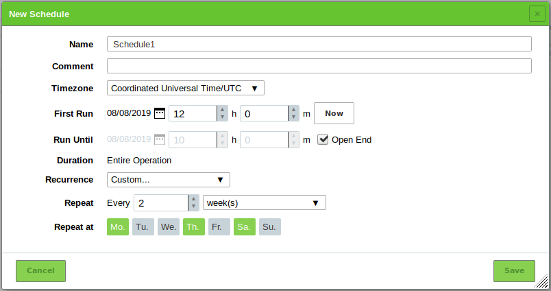
Fig. 10.38 Creating a new schedule
The following details of the schedule can be defined:
- Name
- Definition of the name. The name can be chosen freely.
- Comment
- An optional comment can contain additional information.
- Timezone
Definition of the timezone the time refers to. UTC is default.
Note
Since the GSM runs in the UTC timezone internally, the chosen time zone is very important. For Eastern Standard Time (EST) America/New York has to be selected.
- First Run
Definition of the date and time for the first scan to start.
By clicking
the date can be chosen. By clicking Now the current date and time are set for the first run.- Run Until
Definition of the date and time for the first scan to end.
By clicking
the date can be chosen.
Activate the checkbox Open End to leave the end time open.- Duration
- Definition of the maximum duration a task can take for its execution. The duration depends on the given start and end time. If an end time is defined and the assigned time is expired, the task is aborted and will be suspended until the next scheduled time slot becomes available. This way it can be ensured that the scan will always run with a specific (maintenance) time window.
- Recurrence
- Definition of the repetition rate of the task. It can be selected between Once, Hourly, Daily, Weekly, Monthly, Yearly, Workweeks (Monday till Friday) or Custom. If the option Custom is selected, the repetition rate and the days on which the task should be run can be chosen.
10.10.2. Managing Schedules
List Page
All existing schedules can be displayed by selecting Configuration > Schedules in the menu bar.
For all schedules the following information is displayed:
- Name
- Name of the schedule.
- First Run
- Start time of the first run of the task.
- Next Run
- Next run of the task according to the current date and time.
- Recurrence
- Repetition rate of the task.
- Duration
- Maximum duration a task can take for its execution. The duration depends on the given start and end time. If an end time is defined and the assigned time is expired, the task is aborted and will be suspended until the next scheduled time slot becomes available. This way it can be ensured that the scan will always run with a specific (maintenance) time window.
For all schedules the following actions are available:
- Delete the schedule. Only schedules which are currently not used can be deleted.
- Edit the schedule.
- Clone the schedule.
- Export the schedule as an XML file.
Note
By clicking or below the list of schedules more than one schedule can be deleted or exported at a time. The drop-down-list is used to select which schedules are deleted or exported.
Details Page
Click on the name of a schedule to display the details of the schedule. Click to open the details page of the schedule.
The following registers are available:
- Information
- General information about the schedule.
- User Tags
- Assigned tags (see Chapter 8.5).
- Permissions
- Assigned permissions (see Chapter 9.4).
The following actions are available in the upper left corner:
- Open the corresponding chapter of the user manual.
- Show the list page of all schedules.
- Create a new schedule (see Chapter 10.10.1).
- Clone the schedule.
- Edit the schedule.
 Delete the schedule. Only schedules which are currently not used can be deleted.
- Export the schedule as an XML file.
10.11. Creating and Managing Scanners
The GSM appliance comes with two predefined scanners. They can be managed and new scanners can be created.
The following scanners are already available:
- OpenVAS Default
- CVE: the CVE scanner allows forecasting possible security risks based on current information about known vulnerabilities from the SecInfo management (see Chapter 13) without the need of a new scan (see Chapter 10.4).
Note
The desired scanner for a task is selected when creating the task (see Chapter 10.2.2).
10.11.1. Creating a Scanner
10.11.2. Managing Scanners
List Page
All existing scanners can be displayed by selecting Configuration > Scanners in the menu bar (see Fig. 10.39).

Fig. 10.39 Page Scanners displaying all existing scanners
For all scanners the following actions are available:
- Delete the scanner. Only self-created scanners can be deleted.
- Edit the scanner. Only self-created scanners can be edited.
- Clone the scanner. Only self-created scanners can be cloned.
- Export the scanner as an XML file.
 Verify that the scanner is online and that the manager can connect to it using the provided certificates.
- Download the certificate or CA certificate. The certificate or CA certificate can only be downloaded for self-created scanners.
Note
By clicking or below the list of scanners more than one scanner can be deleted or exported at a time. The drop-down-list is used to select which scanners are deleted or exported.
Details Page
Click on the name of a scanner to display the details of the scanner. Click to open the details page of the scanner.
The following registers are available:
- Information
- General information about the scanner.
- User Tags
- Assigned tags (see Chapter 8.5).
- Permissions
- Assigned permissions (see Chapter 9.4).
The following actions are available in the upper left corner:
- Open the corresponding chapter of the user manual.
- Show the list page of all scanners.
- Create a new scanner (see Chapter 10.11.1).
- Clone the scanner. Only self-created scanners can be cloned.
- Edit the scanner. Only self-created scanners can be edited.
- Delete the scanner. Only self-created scanners can be deleted.
- Export the scanner as an XML file.
- Verify that the scanner is online and that the manager can connect to it using the provided certificates.
10.12. Using Alerts
Alerts are anchored within the system. If a configured event (e.g. a task is finished) happens, a specified condition is checked (e.g. vulnerability with a high severity category detected). If the conditions is met, an action is performed, e.g. an e-mail is sent to a defined address.
10.12.1. Creating an Alert
A new alert can be created as follows:
Select Configuration > Alerts.
Create a new alert by clicking
.Define the alert (see Fig. 10.40).
Click Save.
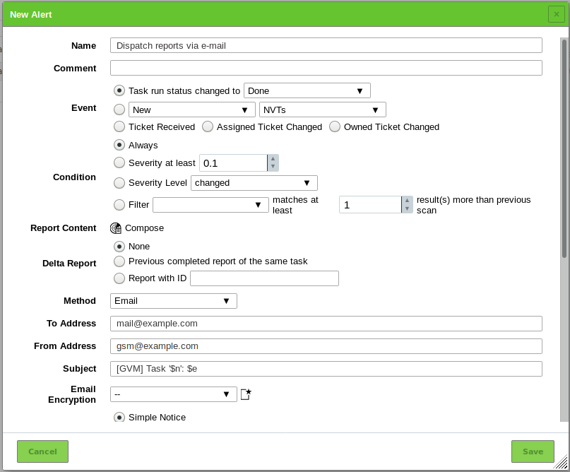
Fig. 10.40 Creating a new alert
The following details of the alert can be defined:
- Name
- Definition of the name. The name can be chosen freely.
- Comment
- An optional comment can contain additional information.
- Event
- Definition of the event for which the alert message is sent. Alerts can be sent if the status of a task changes, if SecInfo (NVTs, CVEs, CPEs, CERT-Bund Advisories, DFN-CERT Advisories, OVAL Definition) is added or updated or if a ticket is assigned or edited (see Chapter 11.6).
- Condition
Definition of the additional conditions that have to be met.
Note
The options differ for task, for SecInfo and for ticket related alerts.
The alert message can occur:
- Always
- If a specific severity level is reached.
- If the severity level changes, increases or decreases.
- If a Powerfilter matches at least the specified number of results more than in the previous scan.
- Report Content (only for task related alerts)
- The report content can be limited with an additional filter.
By clicking the scan report content composer is opened and a Powerfilter can be chosen (see Chapter 11.2.2).
The filter must be created previously (see Chapter 8.4).
- Details URL (only for SecInfo related alerts)
- Definition of the URL from which the SecInfo is obtained.
- Delta Report (only for task related alerts)
- Optionally, a delta report can be created, either in comparison to a previous report or to a report with a certain ID.
- Method
Selection of the method for the alert. Only one method per alert can be chosen. If different alerts for the same event should be triggered, multiple alerts must be created and linked to the same event.
Note
Some methods cannot be used for SecInfo or ticket related alerts.
The following methods are possible:
The report is sent to a given e-mail address.
To use this method the used mail server has to be configured using the GOS administration menu (see Chapter 7.2.10).
The settings To Address, From Address and Content have to be configured for the e-mail alert to work. The e-mail subject and encryption is optional.
- To Address
E-mail address to which the e-mail is sent.
- From Address
E-mail address that is stated as the e-mail’s sender.
- Subject
For the subject the following placeholders can be used:
- $d: the date of the last SecInfo check or blank for task/ticket alerts.
- $e: the event description.
- $n: the task name or blank for SecInfo/ticket alerts.
- $N: the alert name.
- $q: the type of SecInfo event (New, Updated) or blank for task/ticket alerts.
- $s: the SecInfo type (e.g., NVT or CERT-Bund Advisory) or blank for task/ticket alerts.
- $S: see $s, but pluralized (e.g., NVTs, CERT-Bund Advisories) or blank for task/ticket alerts.
- $T: the total number of objects in the list for SecInfo alerts or 0 for task/ticket alerts.
- $u: the owner of the alert or the name of the currently logged in user if the alert was triggered manually.
- $U: the UUID of the alert.
- $$: the dollar sign ($).
- Email Encryption
The e-mail can be encrypted using a configurable S/MIME or GPG key. The key can be selected in the drop-down list Email Encryption or created by clicking
.
The certificate files have to fulfill the following conditions:- PEM encoded (a binary DER file cannot be used)
- Using the X.509 format
- Issued for the recipient e-mail address (To Address) and valid (not expired)
- If the certificate originally came in a bundled format that included the private key as well, only the unencrypted certificate has to be uploaded.
In case of S/MIME credentials, the certificate file additionally has to fulfill the following condition:
- Combines all certificates of the chain (root certificate and all intermediate certificates)
- Content
The content of the e-mail can be a simple notice, an included or an attached report.
Note
The maximum size (in bytes) of reports included in or attached to an e-mail can be limited (see Chapter 7.2.10.2).
- Include Report
- The report can be included directly in the e-mail. Any report format that uses a content type starting with text/ can be chosen because e-mails do not support binary content directly.
- Attach Report
- The report can be attached to the e-mail. Any report format can be chosen. The report will be attached to the generated e-mail in its correct MIME type.
The content of the e-mail message can be edited for both, the included and the attached report. For the message the following placeholders can be used:
- $c: the condition description.
- $d: the date of the last SecInfo check or blank for task/ticket alerts.
- $e: the event description.
- $F: the name of filter.
- $f: the filter term.
- $H: the host summary.
- $i: the report text or list of SecInfo objects (only if including the report/list).
- $n: the task name or blank for SecInfo/ticket alerts.
- $N: the alert name.
- $q: the type of SecInfo event (New, Updated) or blank for task/ticket alerts.
- $r: the name of the report format.
- $s: the SecInfo type (e.g., NVT or CERT-Bund Advisory) or blank for task/ticket alerts.
- $S: see $s, but pluralized (e.g., NVTs, CERT-Bund Advisories) or blank for task/ticket alerts.
- $t: the note if the report was truncated.
- $T: the total number of objects in the list for SecInfo alerts or 0 for task/ticket alerts.
- $u: the owner of the alert or the name of the currently logged in user if the alert was triggered manually.
- $U: the UUID of the alert.
- $z: the timezone.
- $$: the dollar sign ($).
- HTTP Get
The URL is issued as HTTP Get. For example, an SMS text message can be sent via HTTP Get gateway or a bug report can be created in an issue tracker. For the URL the following placeholders can be used:
- $n: the task name or blank for SecInfo/ticket alerts.
- $e: the event description.
- $c: the condition description.
- $$: the dollar sign ($).
- SCP
The report is copied to the given destination via Secure Copy Protocol (SCP) using the given login credentials for authentication.
All settings (credential, host, known hosts and path) have to be configured for the SCP alert to work.
- Credential
- A user name and password or user name and SSH key credential that contains valid login information for the destination system.
- Host
- The host name or IP address of the destination system. Only one destination system per SCP alert is supported.
- Known Hosts
- The SSH public key of the destination system in the format “host protocol public_key”, e.g.,
localhost ssh-rsa AAAAB3NzaC1y...P3pCquVb. The “host” part must match the host name or IP address respectively.
- Path
- The full path of the destination directory and file, e.g.,
/home/user/Downloads/report.xml. Shortening the path, e.g., by using~is not supported. For the file name the following placeholders can be used:- $$: the dollar sign ($).
- $n: the task name.
- Send to host
- The report is sent to an arbitrary host-port-combination via TCP. The format of the report can be chosen from the installed report formats.
- SMB
The report is copied to a given destination using the SMB protocol with the given login credentials.
The share path and the file path must be specified. The share path contains the part of the UNC path containing the host and the share name, e.g. “hostshare”.
Note
If the file path contains subdirectories which do not exist, the necessary subdirectories are created.
For the file path the following placeholders can be used:
- %C: the creation date in the format YYYYMMDD. Changed to the current date if a creation date is not available.
- %c: the creation time in the format HHMMSS. Changed to the current time if a creation time is not available.
- %D: the current date in the format YYYYMMDD.
- %F: the name of the used report format (XML for lists and types other than reports).
- %M: the modification date in the format YYYYMMDD. Changed to the creation date or to the current date if a modification date is not available.
- %m: the modification time in the format HHMMSS. Changed to the creation time or to the current time if a modification time is not available.
- %N: the name for the object or the associated task for reports. Lists and types without a name will use the type (see %T).
- %T: the object type, e.g. “task”, “port_list”. Pluralized for list pages.
- %t: the current time in the format HHMMSS.
- %U: the unique ID of the object or “list” for lists of multiple objects.
- %u: the name of the currently logged in user.
- %%: the percent sign (%).
Note
The file extension is appended corresponding to the format selected in the drop-down-list Report Format.
The default report export file name (see Chapter 8.7) is appended to the file path if the file path ends with
\.Note
If a task uses the tag
smb-alert:file_pathwith a value, then the value is used as the file path instead of the one that has been configured with the alert (see Chapter 8.5).Example:
smb-alert:file_path=alert_1assigns the file pathalert_1.- SNMP
An SNMP trap is sent to the given agent. The provided community is used to authenticate the SNMP trap and the agent is the targeted SNMP trap receiver. For the message the following placeholders can be used:
- $d: the date of the last SecInfo check or blank for task/ticket alerts.
- $e: the event description.
- $n: the task name or blank for SecInfo/ticket alerts.
- $q: the type of SecInfo event (New, Updated) or blank for task/ticket alerts.
- $s: the SecInfo type (e.g. NVT or CERT-Bund Advisory) or blank for task/ticket alerts.
- $S: see $s, but pluralized (e.g., NVTs, CERT-Bund Advisories) or blank for task/ticket alerts.
- $T: the total number of objects in the list for SecInfo alerts or 0 for task/ticket alerts.
- Sourcefire Connector
- The data can be sent to a Cisco Firepower Management Center (formerly known as Sourcefire Defense Center) automatically. For more information see Chapter 18.4.
- Start Task
- The alert can start an additional task. The task is selected in the drop-down-list.
- System Logger
- The alert is sent to a Syslog daemon. The Syslog server is defined using the GOS administration menu (see Chapter 7.2.11).
- verinice.PRO Connector
- The data can be sent to a verinice.PRO installation automatically. For more information see Chapter 18.2.
- TippingPoint SMS
An HTTPS API is used to upload a report in CSV format to the TippingPoint Security Management System (SMS).
- Hostname / IP
- The CSV report is sent to
https://$SMS_ADDRESS/vulnscanner/importwhere$SMS_ADDRESSis replaced by the host name/IP address from the input field.
- Credentials
- A user name and password credential that contains valid login information for the TippingPoint SMS.
- SSL / TLS Certificate
- A CA certificate used to verify that the host the alert connects to is the TippingPoint SMS.
- Use workaround for default certificate
- By default, the certificate uses Tippingpoint as the common name (CN) which does not match the host name/IP address of the TippingPoint SMS in most cases. If enabled, the workaround temporarily changes the CN and resolves it to the actual host name/IP address within the internal connector script.
- Alemba vFire
- A new ticket in the service management application vFire is created. The report can be attached in one or more formats. For more information see Chapter 18.5.
10.12.2. Assigning an Existing Alert to a Task
If an alert should be used afterwards, the alert has to be defined for a specific task as follows:
Note
Already defined and used tasks can be edited as well as it does not have any effect on already created reports.
Select Scans > Tasks in the menu bar.
In the row of the task click
.Select the alert in the drop-down-list Alerts (see Fig. 10.41).
Note
A new alert can be created by clicking
.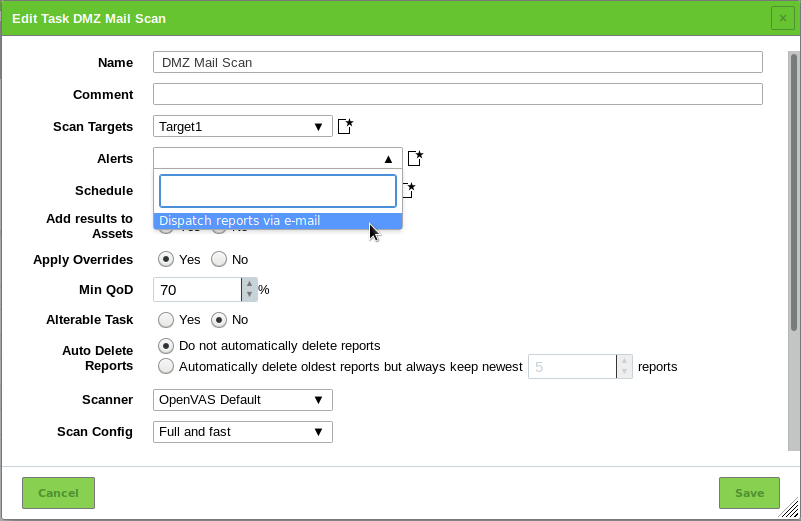
Fig. 10.41 Configuring a task with an alert
Click Save.
→ Afterwards the task using the alert appears on the details page of the alert (see Fig. 10.42).
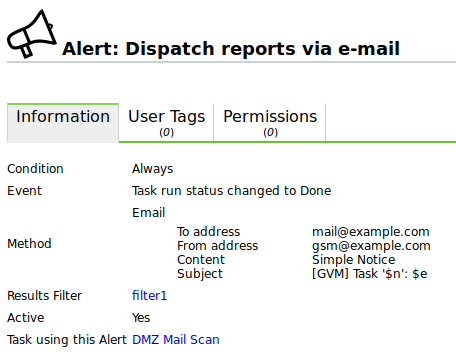
Fig. 10.42 Task using a specific alert
10.12.3. Managing Alerts
List Page
All existing alerts can be displayed by selecting Configuration > Alerts in the menu bar.
For all alerts the following information is displayed:
- Name
- Name of the alert.
- Event
- Event for that the alert is triggered.
- Condition
- Condition that has to be fulfilled to trigger the alert.
- Method
- Chosen alert method with additional information, e.g. to which IP address or e-mail address the alert message is sent.
- Filter (only for task related alerts)
- Filter that is applied to the report content.
- Active
- Indication whether the alert is enabled or disabled.
For all alerts the following actions are available:
- Delete the alert. Only alerts which are currently not used can be deleted.
- Edit the alert.
- Clone the alert.
- Export the alert as an XML file.
- Test the alert.
Note
By clicking or below the list of alerts more than one alert can be deleted or exported at a time. The drop-down-list is used to select which alerts are deleted or exported.
Details Page
Click on the name of an alert to display the details of the alert. Click to open the details page of the alert.
The following registers are available:
- Information
- General information about the alert.
- User Tags
- Assigned tags (see Chapter 8.5).
- Permissions
- Assigned permissions (see Chapter 9.4).
The following actions are available in the upper left corner:
- Open the corresponding chapter of the user manual.
- Show the list page of all alerts.
- Create a new alert (see Chapter 10.12.1).
- Clone the alert.
- Edit the alert.
- Delete the alert. Only alerts which are currently not used can be deleted.
- Export the alert as an XML file.
10.13. Obstacles While Scanning
There are several typical problems which might occur during a scan using the default values of the GSM. While the default values of the GSM are valid for most environments and customers, depending on the actual environment and the configuration of the scanned hosts they might require some tweaking.
10.13.1. Hosts not Found
During a typical scan (either Discovery or Full and fast) the GSM will by default first use the ping command to check the availability of the configured targets. If the target does not reply to the ping request it is presumed to be dead and will not be scanned by the port scanner or any NVT.
In most LAN environments this does not pose any problems because all devices will respond to a ping request. But sometimes (local) firewalls or other configuration might suppress the ping response. If this happens the target will not be scanned and will not be included in the results and the scan report.
To remediate this problem, both the target configuration and the scan configuration support the setting of the alive test (see Alive Test).
If the target does not respond to a ping request, a TCP ping may be tested. If the target is located within the same broadcast domain, an ARP ping may be tried as well.
10.13.2. Long Scan Periods
Once the target is discovered to be alive using the ping command the GSM uses a port scanner to scan the target. By default, a TCP port list containing around 5000 ports is used. If the target is protected by a (local) firewall dropping most of these packets the port scan will need to wait for the timeout of each individual port. If the hosts are protected by (local) firewalls the port lists or the firewalls may be tuned. If the firewall does not drop the request but rejects the request the port scanner does not have to wait for the timeout. This is especially true if UDP ports are included in the scan.
10.13.3. NVT not Used
This happens especially very often if UDP based NVTs like NVTs using the SNMP protocol are used. If the default configuration Full and fast is used, the SNMP NVTs are included. But if the target is configured using the default port list, the NVTs are not executed. This happens because the default port list does not include any UDP ports. Therefore, the port 161/udp (SNMP) is not discovered and excluded from further scans. Both the discovery scans and the recommended scan configuration Full and fast optimize the scan based on the discovered services. If the UDP port is not discovered, no SNMP NVTs are executed.
Do not enable all ports per default in the port lists. This will prolong the scans considerably. Best practice is the tuning of the port lists to the ports which are used in the environment and are supported by the firewalls.
10.13.4. Scanning vhosts
The scanner is able to find all relationships of host names and IP addresses without needing additional user input.
In environments with virtual hosts, the scan reports will have less results because duplicates are avoided.
Two scanner preferences handle vhost scanning (see Chapter 10.9.5):
- test_empty_vhost
- If this preference is enabled, the scanner also tests the target by using empty vhost values in addition to the target’s associated vhost values.
- expand_vhosts
- If this preference is enabled, the target’s host list of vhosts is expanded with values gathered from sources such as reverse lookup queries and VT checks for SSL/TLS certificates.
Footnotes
| [1] | The maximum netmask is /20. This equals 4096 addresses. |