
16. Using a Master-Sensor Setup
Note
This chapter documents all possible menu options.
However, not all GSM types support all of these menu options. Check the tables in Chapter 3 to see whether a specific feature is available for the used GSM type.
Due to security reasons it is often not possible to scan specific network segments directly. For example, direct access to the internet may be prohibited. To overcome this issue, the Greenbone Security Manager (GSM) supports the setup of a distributed scan system: two or more GSMs in different network segments can be connected securely in order to run vulnerability tests for those network segments that are otherwise not accessible.
In this case one GSM controls one or more other GSMs remotely. A controlling GSM is referred to as a “master” and a controlled GSM is referred to as a “sensor”.
Master
- All GSM types of the Midrange Class (physical and virtual) and the Enterprise Class can be used as a master (see Chapter 3).
Sensor
- All GSM types except for GSM ONE/MAVEN can be used as a sensor.
- The GSM types GSM 35 and 25V can only be used as a sensor and are always controlled by a master.
- All sensors can be managed directly by the master including automatic or manual feed updates as well as upgrades of the Greenbone Operating System (GOS).
- A sensor does not require any network connectivity other than to the master and the scan targets
- A sensor does not require any further administrative steps after the initial setup.
- If a sensor should perform scans remotely, it has to be configured as a remote scanner.
- The user can configure a scan for the remote scanner individually using the web interface of the master depending on requirements and permissions.
- The remote scanner runs the scan and relays the results to the master where all vulnerability information is managed.
- The connection to a remote scanner is established by using the Greenbone Management Protocol (GMP) via SSH.
The connection between master and sensor is established using the Secure Shell (SSH) protocol via port 22/TCP.
To distinguish between the sensor and remote scanner terminology:
- Sensors
- This feature requires the setup of the master-sensor link using the GOS administration menu of both the master and the sensor. This feature then supports the remote feed synchronization and the upgrade management of the sensor.
- Remote Scanners
- This feature requires the activation of GMP on the sensor using the GOS administration menu and the setup of the remote scanner using the web interface on the master. This feature then supports the execution of scans via the sensor.
16.1. Configuring a Master-Sensor Setup
16.1.1. Connecting a Master to a Sensor
A master can be linked to a sensor as follows:
Open the GOS administration menu of both the master and the sensor (see Chapter 7.1.2.2).
In the GOS administration menu of the master select Setup and press Enter.
Select Master and press Enter.
Select Master Identifier and press Enter.
Select Download and press Enter (see Fig. 16.1).

Fig. 16.1 Configuring the master
Open the web browser and enter the displayed URL.
Download the PUB file.
→ When the key is downloaded, the GOS administration menu of the master displays the fingerprint of the key for verification.
Important
Do not confirm the fingerprint until the key is uploaded to the sensor.
In the GOS administration menu of the sensor select Setup and press Enter.
Select Sensor and press Enter.
Select Configure Master and press Enter (see Fig. 16.2).
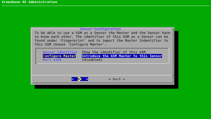
Fig. 16.2 Configuring the sensor
Select Upload and press Enter.
Open the web browser and enter the displayed URL.
Click Browse…, select the previously downloaded PUB file and click Upload.
→ When the key is uploaded, the GOS administration menu of the sensor displays the fingerprint of the key for verification.
Compare the fingerprint to the fingerprint displayed on the GOS administration menu of the master.
If the fingerprints match, press Enter in both GOS administration menus.
In the GOS administration menu of the sensor select Save and press Enter.
Perform twice: press Tab and press Enter.
Select Services and press Enter.
Select SSH and press Enter.
Select SSH State and press Enter.
→ SSH is enabled on the sensor.
Select Save and press Enter.
Note
On the GSM types GSM 25V and GSM 35 the GMP service is always enabled.
If one of these types is used, continue with step 26.
Press Tab and press Enter.
Select GMP and press Enter.
Select GMP-State and press Enter.
→ A message informs that the changes have to be saved (see Chapter 7.1.3).
Press Enter to close the message.
Select Save and press Enter.
In the GOS administration menu of the master select Setup and press Enter.
Select Master and press Enter.
Select Sensors and press Enter.
Select Add a new sensor and press Enter.
Enter the IP address or the host name of the sensor in the input box and press Enter.
→ Additional menu options for the sensor configuration are shown (see Fig. 16.3).
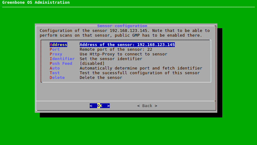
Fig. 16.3 Sensor configuration menu
Select Auto and press Enter.
→ The master connects to the sensor automatically and retrieves the identifier.
The fingerprint of the identifier is displayed on the GOS administration menu of the master.
In the GOS administration menu of the sensor select Setup and press Enter.
Select Sensor and press Enter.
Select Sensor Identifier and press Enter.
Select Fingerprint and press Enter.
Compare the fingerprint to the fingerprint displayed on the GOS administration menu of the master.
If the fingerprints match, press Enter in the GOS administration menu of the master.
Select Save and press Enter.
Select Test and press Enter.
→ The configuration of the sensor is tested.
If the test fails, a warning with instructions is displayed (see Fig. 16.4).
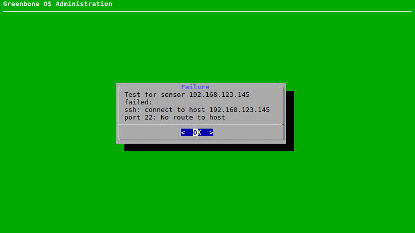
Fig. 16.4 Testing the sensor configuration
16.1.2. Creating a Scan User Account
In addition to linking the master and the sensor, a scan user account on the sensor is required for using the sensor as a remote scanner (see Chapter 16.3). The scan user can be created as follows:
- In the GOS administration menu of the sensor select Setup and press Enter.
- Select User and press Enter.
- Select Users and press Enter.
- Select Admin User and press Enter.
- Determine the user name and the password of the scan user and press Tab.
- Press Enter.
16.2. Deploying Sensors in Secure Networks
For master-sensor setups the master stores all vulnerability information and credentials. A sensor does not store any information permanently (except for NVTs).
Due to this the master needs to be placed in the highest security zone with communication to the outside (to the sensors). All communication is initiated from the master in the higher security zone down to the sensor in the lower security zone.
Note
A firewall separating the different zones only needs to allow connections from the master to the sensor. No additional connections need to be allowed into the higher security zone.
Master and sensor appliances communicate via the SSH protocol. Port 22/TCP is used by default. For backward compatibility port 9390/TCP can be used. This can be configured as follows:
- In the GOS administration menu of the sensor select Setup and press Enter.
- Select Sensor and press Enter.
- Select Port 9390 and press Enter.
- Select Save and press Enter.
On sensors Greenbone Security Feed (GSF) updates and GOS upgrades can be downloaded either directly from the Greenbone Networks servers or using the master. In the second case only the master contacts the Greenbone Networks servers and distributes the corresponding files to all connected sensors. To prevent the sensor from contacting the Greenbone Networks servers, automatic synchronization can be disabled as follows:
- In the GOS administration menu of the sensor select Setup and press Enter.
- Select Feed and press Enter.
- Select Synchronisation and press Enter.
- Select Save and press Enter.
Tip
As an additional layer of security a source and destination NAT rule on a firewall using stateful packet inspection (SPI) can be used to avoid the need of default routes on the GSM appliances.
16.3. Configuring a Sensor as a Remote Scanner
Note
In order to configure a sensor as a remote scanner, all steps in Chapter 16.1.1 have to be completed first.
Sensors can be used as remote scanning engines (scanners) on the master in addition to the default OpenVAS and CVE scanners. For this, the sensor must be configured as a remote scanner using the web interface of the master.
Note
Since the communication between the master and the remote scanner is based on GMP, a remote scanner is referred to as a GMP scanner.
A new remote scanner can be configured as follows:
Log into the web interface of the master.
Select Configuration > Scanners in the menu bar.
Create a new scanner by clicking
 .
.Enter the name of the remote scanner in the input box Name (see Fig. 16.5).
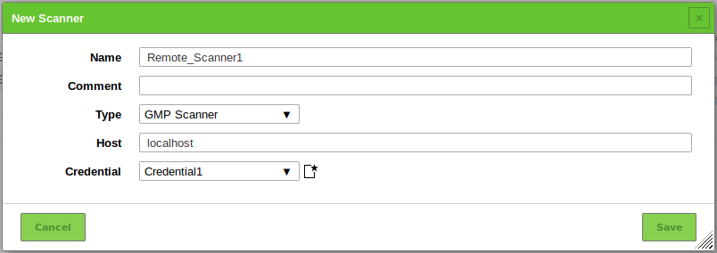
Fig. 16.5 Configuring the remote scanner on the master
Select GMP Scanner in the drop-down-list Type.
Enter the IP address or the host name of the sensor in the input box Host.
Create a new credential by clicking
.Enter the name of the credential in the input box Name.
Select Username + Password in the drop-down-list Type.
Enter the account information of the scan user account (see Chapter 16.1.2) in the input boxes Username and Password.
Click Save to create the credential.
Click Save to create the remote scanner.
→ The scanner is created and displayed on the page Scanners.
In the row of the newly created remote scanner click
 to verify the scanner.
→ If the setup is correct, the scanner is successfully verified.
Tip
Scanners are configured on a per-user basis. Scanners can be created for each user or permissions can be used to grant usage rights to other users (see Chapter 9.4).
16.4. Using a Remote Scanner
After a sensor is configured as a remote scanner, scan tasks can be configured on the master to run on the sensor (see Chapter 10.2.2).
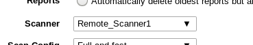
Fig. 16.6 Selecting the remote scanner for a task
If an existing task is marked as alterable  in the column Name on the page Tasks (see Chapter 10.8) the task can be sent to a remote scanner as follows:
- Select Scans > Tasks in the menu bar.
- In the row of the task click
 .
. - Select the remote scanner in the drop-down-list Scanner (see Fig. 16.6).
- Click Save.
- Start the task by clicking
 .
.